
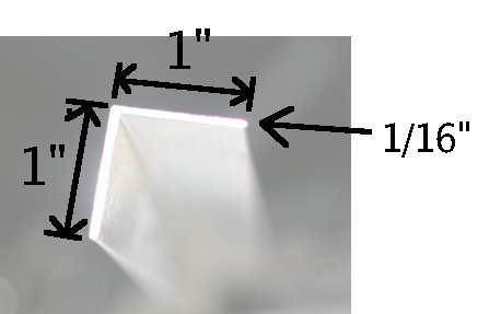
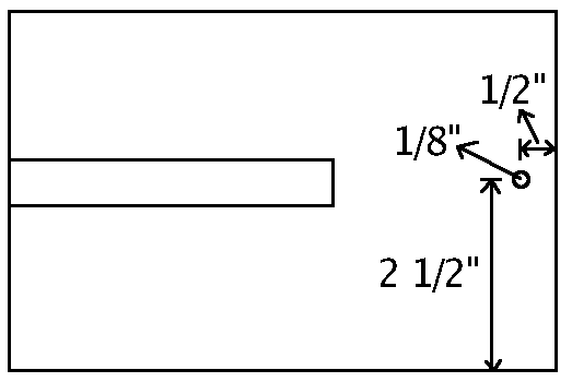
This is what the end of a 1/16" angle aluminum looks like:
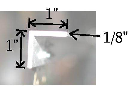
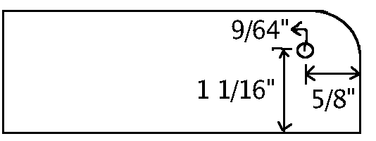
This is what the end of a 1/8" angle aluminum looks like:
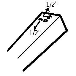
Attachments to the end of a piece of aluminum are common. Attachments to the end of one piece of aluminum always use a 9/64" hole 1/2" from the edge of the piece.
Right angles between 2 pieces of aluminum are common. All right angles are formed by first drilling the end hole for one piece 1/2" from its end, then stacking the piece on the other piece at a right angle and finishing the hole through the other piece.
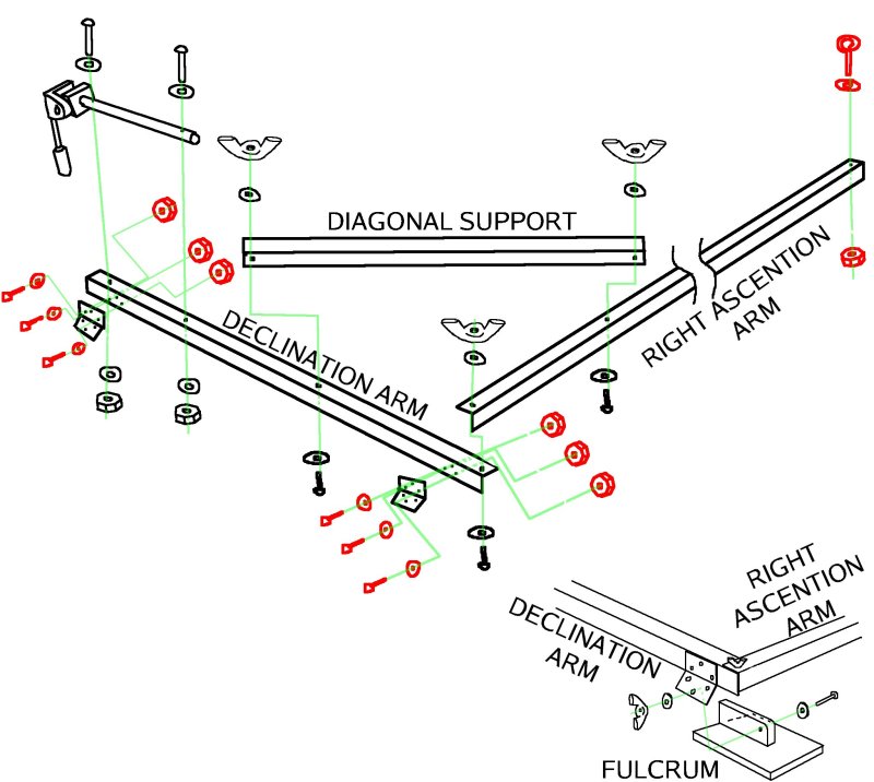
This is a trapezoidian with all the pieces of aluminum and wood labeled.


The diagonal support should have square ends, not bevelled ends as in some pictures. That was a failed experiment. The square ends should extend beyond the arms.
The following pieces of 1/16" angle aluminum are cut out for the various components:
Right ascention arm:         62"
Diagonal support:            25"
Declination triangle:        22.5" * 2  ,   2" * 2
Declination adjustment:      9"         ,   6"
Right ascention triangle:    20"        ,   24"     ,   2.5"
Servo drive:                 28"
Only one length of 1/8" angle aluminum is used:
Declination arm: 35"In the blowup diagrams, the following color codes are used for nut, washer, and bolt sets:
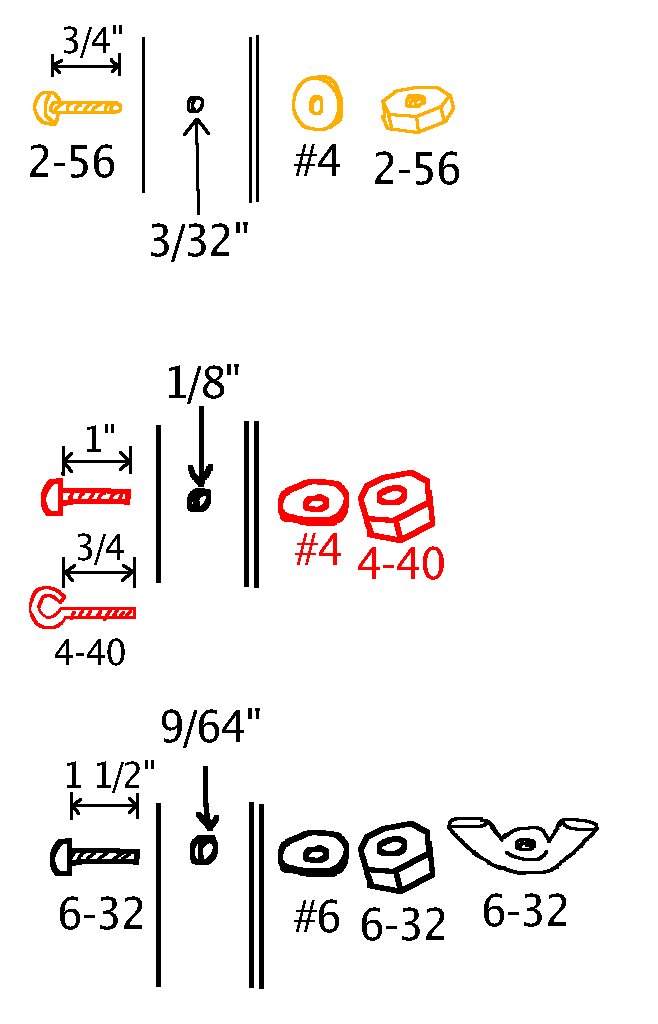
Each bolt has a corresponding hole size. Bolts are cut to the required length + 1/8" when assembly is finished. Whenever a part must be tightened in the field, a wing nut is used.
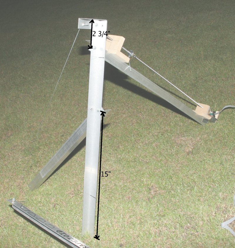
FULCRUM MEASUREMENTS:
The following holes are drilled in the fulcrum pieces:
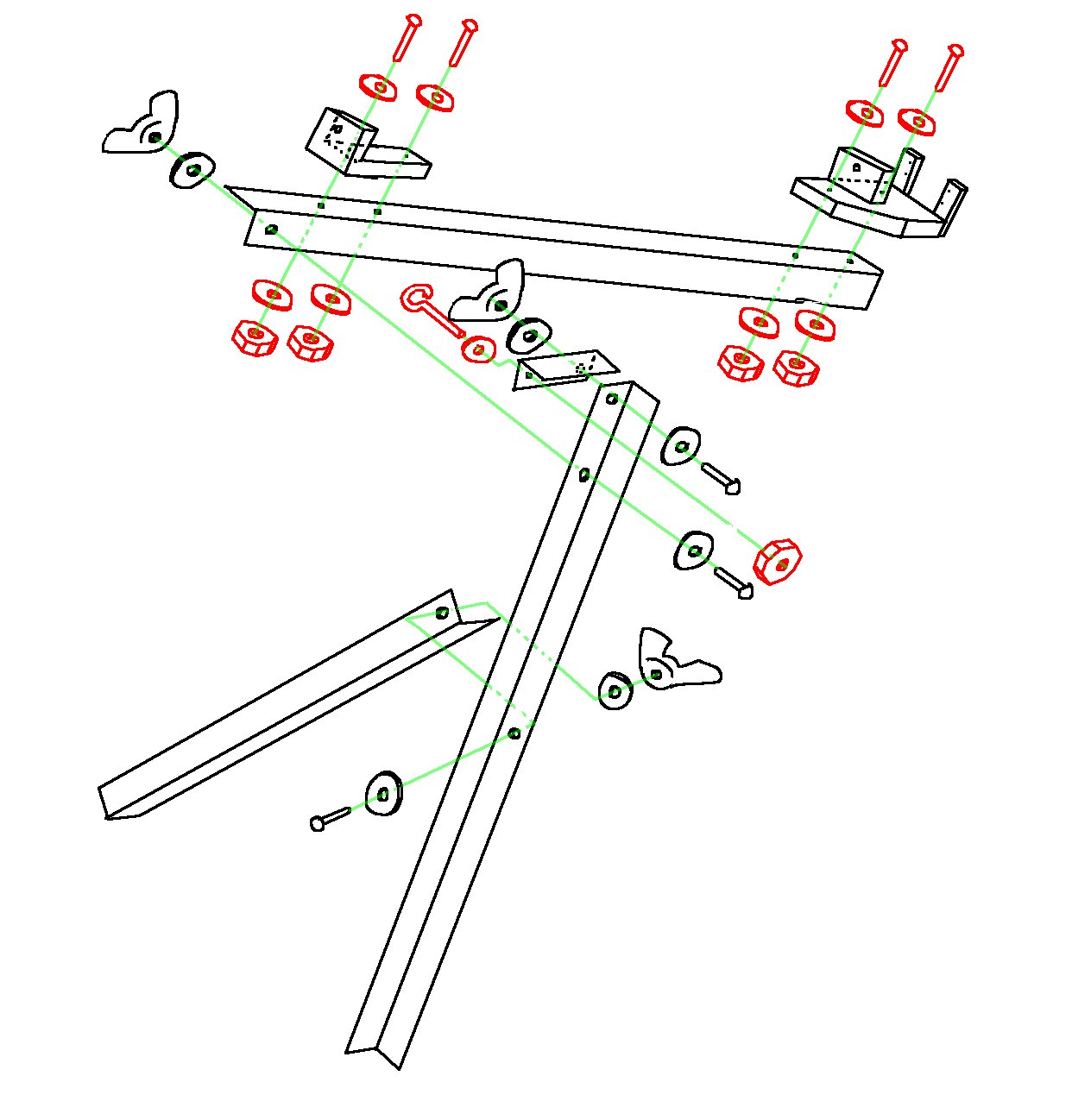
Blowup diagram of the moving part, showing the bolt types and positions:
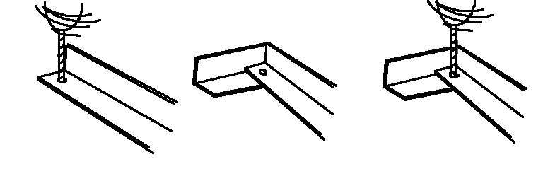
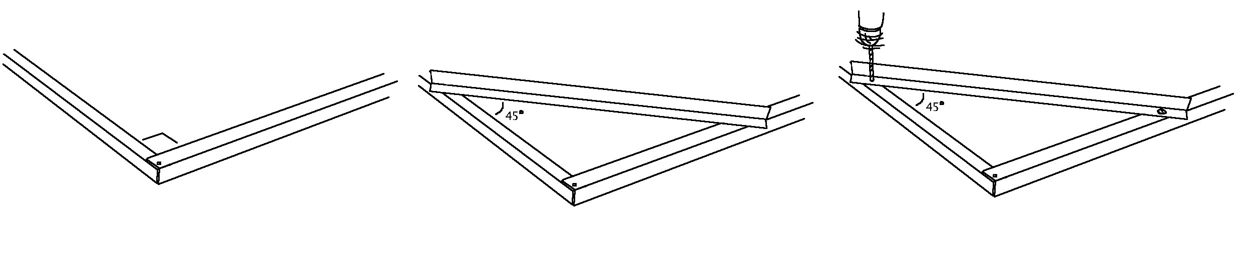
The position of the diagonal support must be determined by locking the
two arms at a 90° angle and placing it at a 45° angle far enough
from the fulcrom to have the ends line up with the arms.
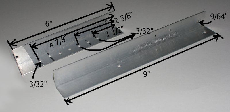
DECLINATION ARM MEASUREMENTS:
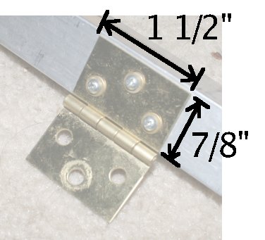
Two of the following hinges are required:
The tripod head was taken from the cheapest available tripod. The tripod head plus 14" of the center rod were cut out of the original tripod. 9/64" holes were drilled through the rod and the declination arm. It was permanently attached with bolts. A more expensive tripod head with pan/tilt worm gears would simplify alignment but defeat the purpose of the trapezoid. We don't recommend ball heads because you need to adjust right ascention independantly of declination to reset.
 Measurements of hinge positions and overlap of the tripod head.
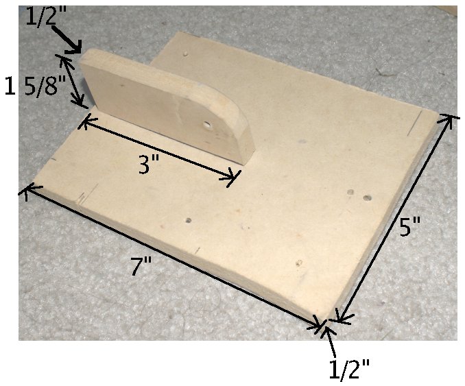
The following pieces are all made of 1/2" thick MDF except the servo mounting sticks. Those have to be spruce.
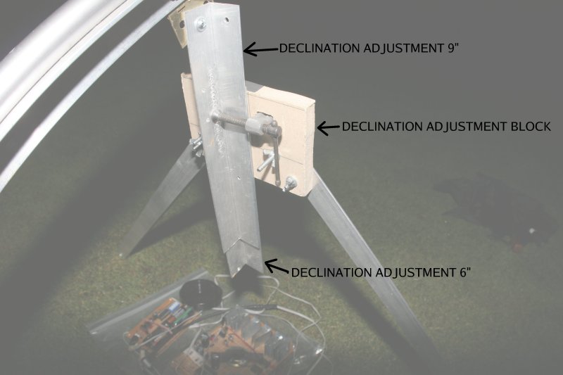
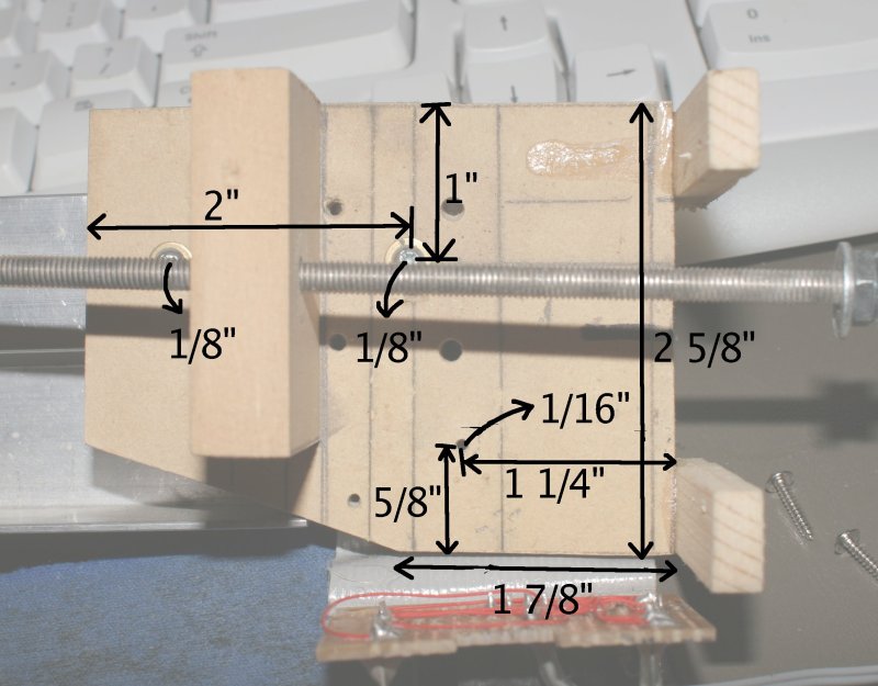
DECLINATION ADJUSTMENT BLOCK:
Measurements of holes in the declination adjustment block. The round holes need to line up with pieces of aluminum so they must be drilled through the wood and aluminum in one movement with the aluminum pieces fixed.

Measurements of holes in the declination adjustment aluminum. Only the necessary holes are measured. The other holes were experimental. Unless otherwise noted, holes are roughly equidistant from both sides of the rod. End holes are 1/2" from the end.
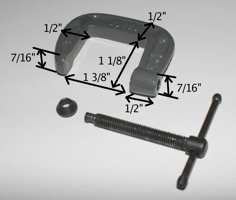
Measurements of the clamp in the declination adjustment block:
Blowup diagram of declination triangle and declination adjustment:

SERVO DRIVE:
 Right ascention triangle attachments
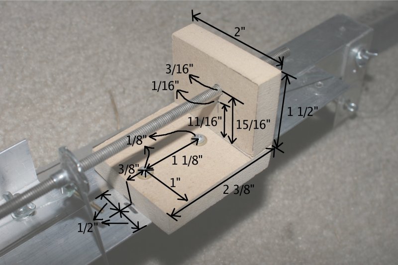 Corkscrew block dimensions.
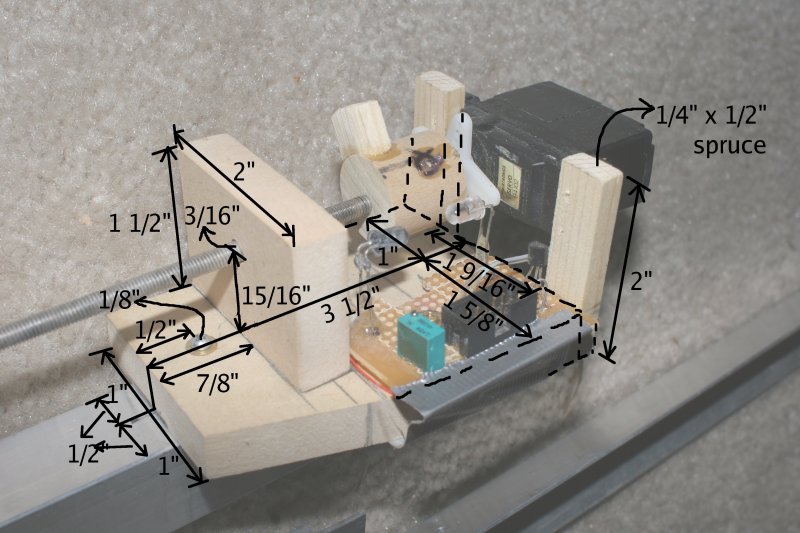
 Servo block dimensions.
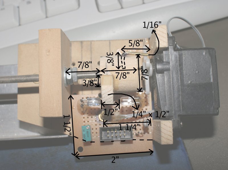
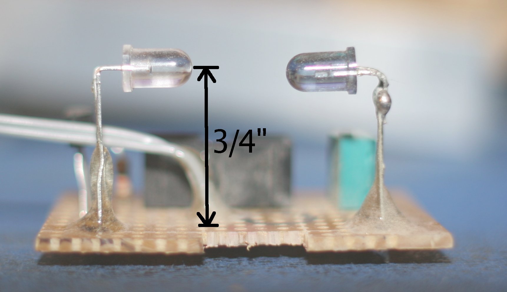
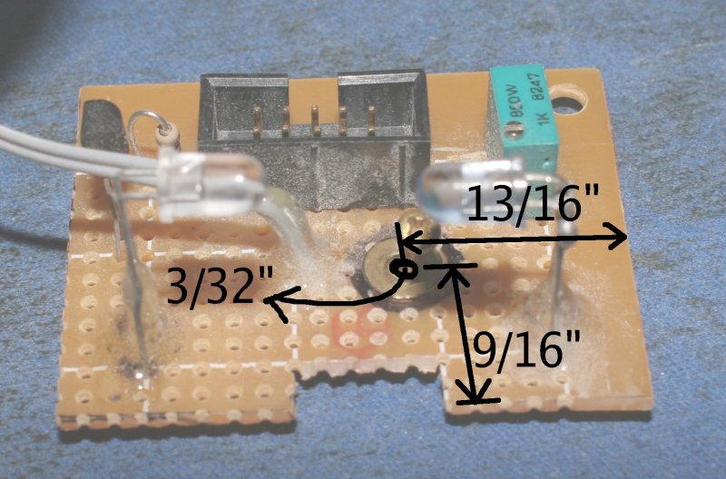
 Measurement of the corkscrew and servo drive attachments.
 Blowup of the right ascention triangle.
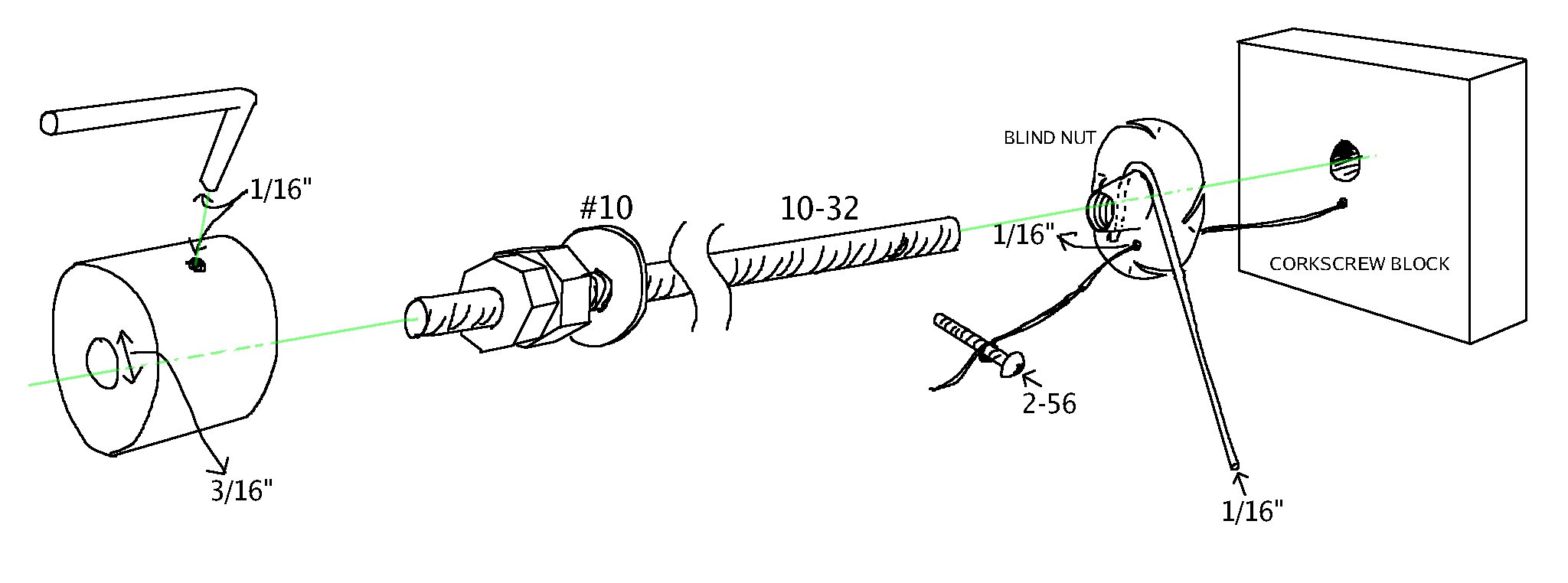 Blowup of the corkscrew.
The basis of the corkscrew mechanism was a threaded 10-32 rod. A 10-32 blind nut with the blades pressed flat formed the pinion of the corkscrew. The fishing line was anchored to the blind nut with a 2-56 bolt.
A 1/16" hole was drilled into the blind nut for the fishing line. Then the blind nut was pressed flat on the corkscrew block and lined up with the corkscrew hole. The 1/16" hole was extended through the corkscrew block. It was critical that the 1/16" hole was directly below the corkscrew hole.
A 1/16" steel rod long enough to reach from the blind nut to hit the right edge of the aluminum was bent around the blind nut and soldered in place. This rod had to be angled such that the 1/16" holes lined up exactly when the 1/16" rod was pressed against the aluminum.
A #10 washer and a pair of counter turned nuts pressed against the servo block and prevented the corkscrew from being pulled away from the servo.
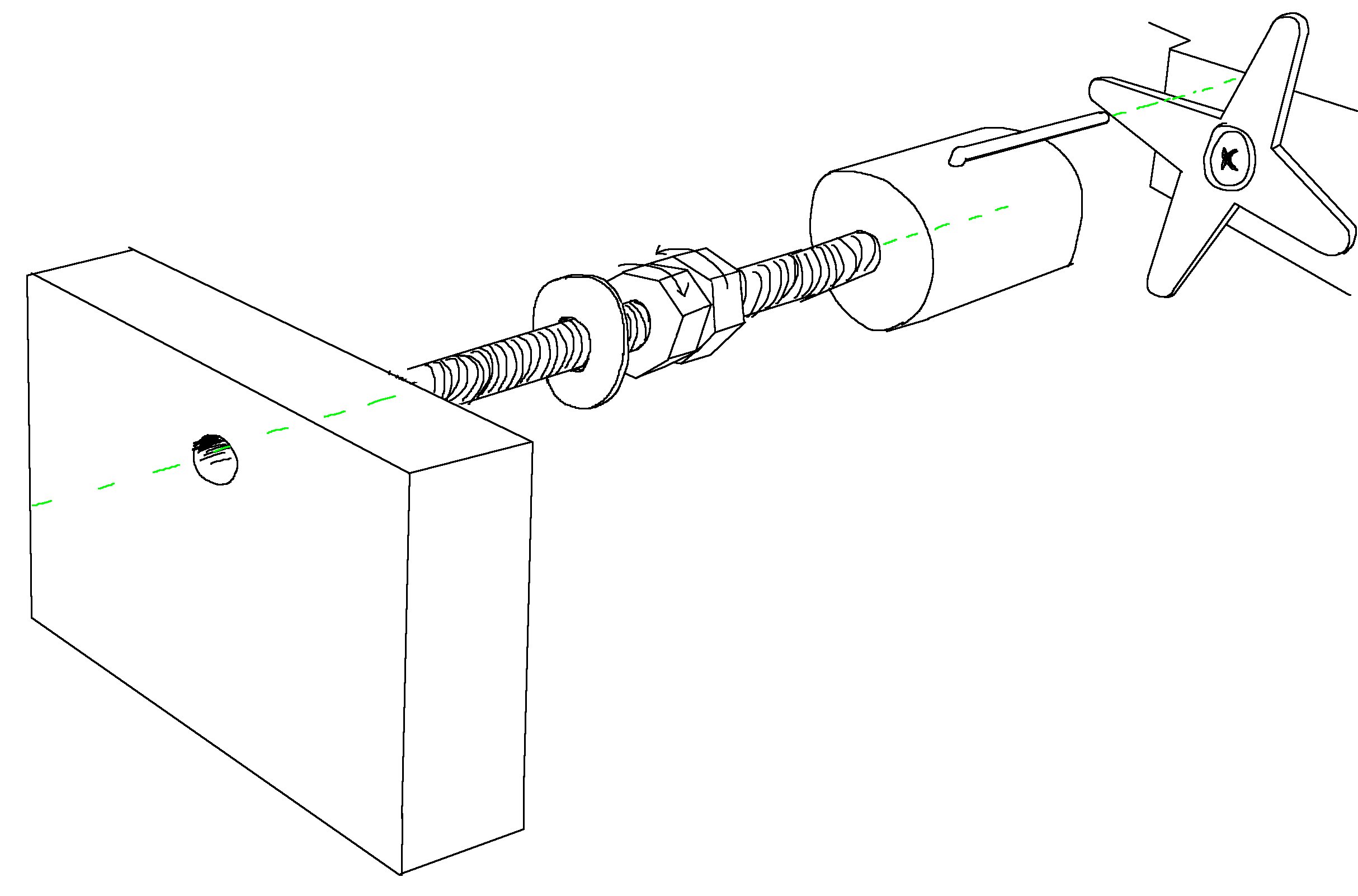
A hole was drilled down the center of a 7/8" dowell for the corkscrew and the corkscrew was screwed in.
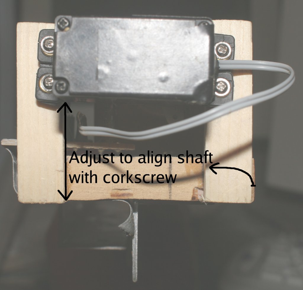
Another 1/16" hole was drilled into the dowell side and a bent 1/16" steel rod was glued into the hole so the other end could stick through the servo head. The end stuck into the dowell had to be short enough to leave room for the corkscrew. The end sticking through the servo head had to be cut short once the servo and corkscrew were installed, to leave room for the servo.
TRANSPORTING THE TRAPEZOID
To transport the trapezoid, the diagonal support is unbolted. The right ascention arm is unbolted from the declination arm. The two hinges are unbolted. The outer bolts on the declination triangle legs are removed and the legs are folded parallel. The fishing line is left attached, but the right ascention triangle members are folded parallel. All the parallel members are strapped together with bungy cord.