Next: ABOUT CINELERRA, Up: (dir) [Contents]
| • ABOUT CINELERRA: | Cinelerra in brief. | |
| • INSTALLATION: | Making Cinelerra work on your system. | |
| • CONFIGURATION: | Adjusting the behavior of Cinelerra. | |
| • CREATING A NEW PROJECT: | Creating a new project | |
| • THE MAIN WINDOWS: | The most often used user interfaces. | |
| • LOADING AND SAVING FILES: | Moving media between disk and Cinelerra. | |
| • NAVIGATING THE PROJECT: | Moving around the media. | |
| • EDITING: | Moving the media in time. | |
| • GENERAL EFFECT USAGE: | How to process media. | |
| • SETTING PROJECT ATTRIBUTES: | Changing the way the media is displayed. | |
| • COMPOSITING: | Overlaying different sources of video. | |
| • KEYFRAMES: | Making effects change over time. | |
| • CAPTURING MEDIA: | Moving media from the real world to disk. | |
| • IMPROVING PERFORMANCE: | Making Cinelerra run better on Linux. | |
| • TROUBLESHOOTING: | Problems with Cinelerra. | |
| • APPLICATION NOTES: | Unusual applications of Cinelerra to common problems. | |
| • EFFECTS NOTES: | How to use various effects. | |
| • PLUGIN AUTHORING: | How to write new effects. | |
| • KEYBOARD SHORTCUTS: | How to accelerate most commands with the keyboard. |
Next: INSTALLATION, Previous: TOP, Up: TOP [Contents]
It’s important to remember where it came from to differentiate what’s really needed from bloat.
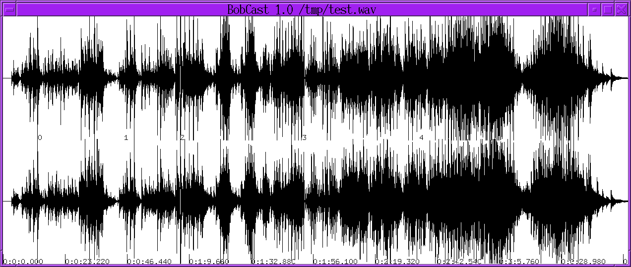
BOBCAST/BROADCAST 1.0
The 1st attempt at editing media was written in 1996. It just loaded a single WAV file or edit list from the command line & shifted bits of it around in a single window. Then it could render a new wav file or save the edit list. It used bare X11 calls & no toolkit.
The typical source in those days was 1 file containing a complete recording session. Editing just needed to move bits of the 1 file around.
Its big magic tricks wer handling files up to 2 gigabytes with only 64 megs of RAM & non destructive editing. That was a feature normally only accessible to the highest end professional audio houses in those days.
BROADCAST 2.1
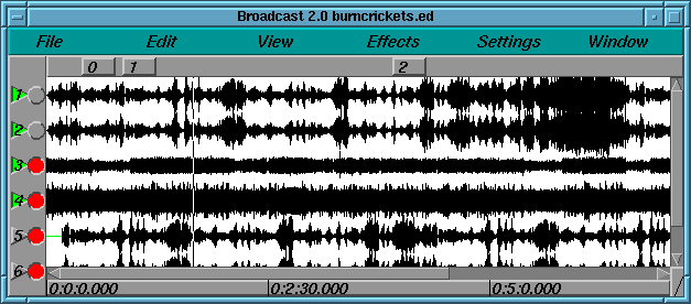
In 1997 Broadcast 1.0 was replaced by Broadcast 2.0. This time the window had a menubar, patchbay, console, and transport control. Broadcast 2.0 still only handled audio but this time it handled unlimited tracks, and it could perform effects on audio and save the resulting waveform to disk. More notably a few effects could be performed as the audio was playing back, in realtime. A user could mix unlimited numbers of tracks, adjust fade, pan, and EQ, and hear the result instantly. Amazingly this real time tweaking is still unavailable on most audio programs.
BROADCAST 2000
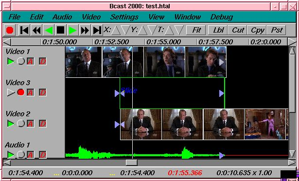
But Broadcast 2.0 still didn’t handle video and it wasn’t very graceful at audio either. In 1999 video broke into the story with Broadcast 2000. This iteration of the Broadcast series could do wonders with audio and offered a pretty good video feature set. It could edit video files up to 64 terabytes. It could do everything Broadcast 2.1 did with audio except now all effects for video and audio could be chained and performed on the fly, with instant feedback as a user tweeked parameters during playback. Broadcast 2000 made it very easy to do a lot of processing and editing on video and audio that would otherwise involve many hours setting up command line sequences and writing to disk. For a time it seemed as if the original dream of immersive movie making for everyone regardless of income level had arrived.
Later on Broadcast 2000 began to come short. Its audio and video was graceful if you knew how to use it efficiently, but quality issues and new user interface techniques were emerging. Broadcast 2000 kept the audio interface from its ancestors, which didn’t apply well to video.
Users likewise were maturing. No longer was it sufficient to just edit video on a UNIX box. Most users expected on UNIX the same thing they got in Win or Mac. A lot of users complained about the lack of support & wanted it taken down if it wasn’t supported. Then a lot of users complained that it was taken down.
CINELERRA
In mid 2000, a Broadcast 2000 replacement began. The Broadcast name was officially retired from the series and the software would now be called Cinelerra. Cinelerra would begin to emulate some of the features found in Win and Mac software while not attempting to become a clone. Helas, not strictly adhering to standard features has been the biggest source of contention.
As with Broadcast 2000, most users oppose this program being distributed without full support, full patch debugging & integration, adherence to standard features, & want it taken down. Whether someone should be allowed to do their own thing is an ages old question. Other projects got ahead of the support problem from the beginning by raising enough funds for full time employment, but doing so requires adhering to accepted designs & features they’re not always fond of.
LINUX DERIVATIVES
Linux became more and more fragmented after corporations adopted it. Threading once worked the same on all derivatives. Today there are more threading models than days of the week. We try to focus on 1 of the most popular Linux derivatives at any moment. The threading model is ported to that Linux derivative shortly before a release, but Linux derivatives quickly evolve to new threading models and everything breaks.
Also, there is no consistent behaviour for sound and video drivers. The situation with video capture has improved in that modern video sources can all be mounted like disk drives. The audio capture drivers have been a bit more reliable.
| • ABOUT THIS MANUAL: |
Up: ABOUT CINELERRA [Contents]
This is the original manual for Cinelerra. This manual has been copied and translated into many languages on many websites in varying degrees of completeness.
Organizing information in the easiest manner for users to find out what they need to know is sort of like cataloging the internet. They’ve been trying to get it right for 30 years and will probably keep trying until the end of time.
There a lot of fragments of documentation scattered throughout the internet about Cinelerra. This document attempts to combine all the pieces of information in one piece.
Like the operating system and compiler for a piece of software, the document writing format is the most important thing in choosing our document format. We wanted a format which would be readable regardless of corporate whims and fads. A piece of software which compiles on GCC and Linux will be usable as long as there are C compilers. Documents written in Texinfo will be readable as long as there’s a C compiler.
After many years of searching for the perfect documentation format we’ve arrived at TexInfo. This format can be converted to HTML, printed, automatically indexed, but most importantly is not bound to any commercial word processor.
There are few screenshots in this manual. Screenshots become obsolete quickly and as a result get confusing. What looks one way in a screenshot will always look different in the real program because the real program and the manual are always evolving, never perfectly synchronized. It is true that manuals should have screenshots, but our objective in omitting screenshots is to keep the software costs minimal so you don’t have to pay for it. That includes additional labor to synchronize the manual with the software.
In addition to telling you the basic editing features of Cinelerra this manual covers tricks that won’t be described anywhere else. We’re going to try to come up with certain things you can do with Cinelerra that you wouldn’t think of on your own.
Next: CONFIGURATION, Previous: ABOUT CINELERRA, Up: TOP [Contents]
The Cinelerra package contains Cinelerra and most of the libraries needed to run it. We try to include all the dependencies because of the difficulty in tracking down the right versions. Also included are some utilities for handling files. The following are the general contents of all Cinelerra packages.
| • INSTALLING A PRECOMPILED BINARY: | ||
| • COMPILING FROM SCRATCH: | ||
| • RUNNING CINELERRA: |
Next: COMPILING FROM SCRATCH, Up: INSTALLATION [Contents]
Cinelerra is easiest installed by downloading a precompiled binary and running
tar xvf cinelerra*.tar.xz
cd cinelerra*
./cinelerra.sh
It should have all the hardest dependencies already taken care of.
This doesn’t always work because there are many versions of libc, each incompatible with the others. This is the biggest reason to compile from scratch.
Next: RUNNING CINELERRA, Previous: INSTALLING A PRECOMPILED BINARY, Up: INSTALLATION [Contents]
It should be noted that the compiler used in building Cinelerra binaries is the free GNU compiler and very conservative optimization flags. Alternative optimization flags and compilers produce varying results. Compiling the source is hard and there’s no warranty if the source code fails to compile, but the method for compiling starts by downloading the source code and decompressing.
The compilation is verified on a vanilla Ubuntu installation of a certain version. It has a lot of dependencies. The README file contains more info on the dependencies.
tar xvf cinelerra*.tar.xz
Enter the main directory
cd cinelerra*
Then run
./configure
This checks the build environment for the right tools and should give you an error if a tool is missing. Once that succeeds run
make
The make procedure should run through all the directories and put binaries in the i686 or x86_64 directories.
A lot of libraries are included in thirdparty directories to get the version numbers right.
Once finished, run
make install
to install the binaries in the bin/ sub directory. It doesn’t install anything in the system folders.
Previous: COMPILING FROM SCRATCH, Up: INSTALLATION [Contents]
The simplest way to run Cinelerra is by going into bin/ & running
./cinelerra.sh
This command hides a much more capable command line interface. Run cinelerra -h to get a listing of command line options. The use of these options is described in several sections.
For rendering from the command line See RENDERING FILES.
Next: CREATING A NEW PROJECT, Previous: INSTALLATION, Up: TOP [Contents]
Because of the variety of uses, Cinelerra cannot be run optimally without some intimate configuration for your specific needs. Very few parameters are adjustable at compile time. Runtime configuration is the only option for most configuration because of the multitude of parameters.
Here we discuss not only the configuration options but which of the different API’s in Linux are supported.
Go to settings->preferences and to see the options.
| • ENVIRONMENT VARIABLES: | These environment variables are recognized by Cinelerra | |
| • AUDIO DRIVERS: | Information about the audio drivers | |
| • VIDEO DRIVERS: | Information about the video drivers | |
| • PLAYBACK: | Configuring parameters related to playback. | |
| • RECORDING: | Configuring parameters related to recording. | |
| • PERFORMANCE: | Configuring parameters related to how fast things go. | |
| • INTERFACE: | Configuring the user interface. | |
| • ABOUT: | Viewing information about the program. |
Next: AUDIO DRIVERS, Up: CONFIGURATION [Contents]
In UNIX derivatives, environment variables are global variables in the shell which all applications can read. They are set with a command like set VARIABLE=value. All the environment variables can be viewed with a command like env. Cinelerra recognizes the following environment variables:
Next: VIDEO DRIVERS, Previous: ENVIRONMENT VARIABLES, Up: CONFIGURATION [Contents]
The audio drivers are used for both recording and playback to get data to and from the hardware. Since the same drivers are used for both recording and playback, their functionality is described here in a separate section. The most tested driver is ALSA.
| • COMMON SOUND DRIVER ATTRIBUTES: | Attributes used for more than one sound driver. | |
| • OSS: | Notes about the OSS driver | |
| • OSS Envy24: | Notes about the OSS driver for the Envy24 chip | |
| • ALSA: | Notes about the ALSA driver | |
| • ESOUND: | Notes about the ESound driver | |
| • RAW 1394: | Notes about the Raw1394 driver | |
| • DV 1394: | Notes about the DV1394 driver | |
| • IEC 61883: | Notes about the IEC 61883 driver |
Next: OSS, Up: AUDIO DRIVERS [Contents]
Usually a file in the /dev/ directory which controls the device.
The number of bits of precision Cinelerra should set the device for. This sometimes has a figuritive meaning. Some sound drivers need to be set to 32 bits to perform 24 bit playback and won’t play anything when set to 24 bits. Some sound drivers need to be set to 24 bits for 24 bit playback.
Next: OSS Envy24, Previous: COMMON SOUND DRIVER ATTRIBUTES, Up: AUDIO DRIVERS [Contents]
This was the first Linux sound driver. It had an open source implementation and a commercial implementation with more sound cards supported. It was the standard sound driver up to linux 2.4. It still is the only sound driver which an i386 binary can use when running on an x86_64 system.
Next: ALSA, Previous: OSS, Up: AUDIO DRIVERS [Contents]
The commercial version of OSS had a variant for 24 bit 96 Khz soundcards. This variant required significant changes to the way the sound drivers were used, which is what the OSS Envy24 variant is for.
Next: ESOUND, Previous: OSS Envy24, Up: AUDIO DRIVERS [Contents]
ALSA is the most common sound driver in Linux. It supports the most sound cards now. For many years, the ALSA API was constantly changing but it’s pretty stable today.
Next: RAW 1394, Previous: ALSA, Up: AUDIO DRIVERS [Contents]
ESOUND was a sound server that sat on top of OSS. It was written for a window manager called Enlightenment. It supported a limited number of bits and had high latency compared to modern times but multiplexed multiple audio sources. It’s unknown whether it still works.
Next: DV 1394, Previous: ESOUND, Up: AUDIO DRIVERS [Contents]
The first interface between linux software and firewire camcorders. This was the least reliable way to play audio to a camcorder. It consisted of a library on top of the kernel commands.
Next: IEC 61883, Previous: RAW 1394, Up: AUDIO DRIVERS [Contents]
The second rewrite of DV camcorder support in Linux. This was the most reliable way to play audio to a camcorder. This consisted of direct kernel commands.
Previous: DV 1394, Up: AUDIO DRIVERS [Contents]
The third rewrite of DV camcorder support in Linux. This is a library on top of RAW 1394 which is a library on top of the kernel commands. It’s less reliable than DV 1394 but more reliable than RAW 1394. The next rewrite ought to fix that.
Next: PLAYBACK, Previous: AUDIO DRIVERS, Up: CONFIGURATION [Contents]
The audio drivers are used for both recording and playback to get data to and from the hardware. Since the same drivers are used for both recording and playback, their functionality is described here in a separate section.
| • COMMON VIDEO DRIVER ATTRIBUTES: | Parameters used by more than one driver. | |
| • X11: | ||
| • X11-XV: | ||
| • X11-OPENGL: | ||
| • BUZ: | ||
| • RAW 1394 VIDEO PLAYBACK: | ||
| • DV 1394 VIDEO PLAYBACK: | ||
| • IEC 61883 VIDEO PLAYBACK: |
Next: X11, Up: VIDEO DRIVERS [Contents]
The is intended for dual monitor displays. Depending on the value of Display, the Compositor window will appear on a different monitor from the rest of the windows.
Usually a file in the /dev/ directory which controls the device.
Make the even lines odd and the odd lines even when sending to the device. On an NTSC or 1080i monitor the fields may need to be swapped to prevent jittery motion.
Devices with multiple outputs may need a specific connector to send video on.
The IEEE1394 standard specifies something known as the port. This is probably the firewire card number in the system to use.
The IEEE1394 standard specifies something known as the channel. For DV cameras it’s always 63.
Next: X11-XV, Previous: COMMON VIDEO DRIVER ATTRIBUTES, Up: VIDEO DRIVERS [Contents]
This was the first method of video playback on any UNIX system, valid all the way until 1999. It just writes the RGB triplet for each pixel directly to the window. It’s the slowest playback method. It’s still useful as a fallback for incompatible graphics hardware.
Next: X11-OPENGL, Previous: X11, Up: VIDEO DRIVERS [Contents]
This was the second big method of video playback in UNIX starting in 1999. It converts YUV to RGB in hardware with scaling. It was the preferred playback method for many years but can’t handle large frame sizes. The maximum video size for XV is hardware dependent & usually 1920x1080.
Next: BUZ, Previous: X11-XV, Up: VIDEO DRIVERS [Contents]
The most powerful video playback method is OpenGL but support is completely hardware dependent. Although the OpenGL API was originally supposed to be hardware independent, it only ended up getting supported by NVidia with other brands moving to OpenCL or Vulcan.
With this driver, most effects are done in the GPU. OpenGL allows video sizes up to the maximum texture size, which is usually larger than 4096x4096, depending on the graphics driver.
Today, the rendering as well as the playback can be done in OpenGL. It relies on PBuffers and shaders to do video rendering. The graphics driver must support OpenGL 2 and Cinelerra needs to be explicitly compiled with OpenGL 2 support. This requires compiling it on a system with the OpenGL 2 headers.
PBuffers are known to be fickle. If the graphics card doesn’t have enough memory or doesn’t have the right visuals, PBuffers won’t work. Try seeking several frames or restarting Cinelerra if OpenGL doesn’t work.
X11-OpenGL processes everything in floating point. Although the difference between YUV and RGB is retained, there is no speed difference when using alpha or floating point color models.
The scaling equation in Preferences is ignored by OpenGL. OpenGL always uses linear scaling.
To get the most acceleration, OpenGL-enabled effects must be placed after software-only effects. All rendering before the last software-only effect is done in software. The core operations like camera and projector are of course OpenGL.
Next: RAW 1394 VIDEO PLAYBACK, Previous: X11-OPENGL, Up: VIDEO DRIVERS [Contents]
This is a method for playing motion JPEG-A files directly to a composite analog signal. It uses a popular hack of the Video4Linux 1 driver from 2000 to decompress JPEG in hardware. Sadly, even though analog output is largely obsolete, newer drivers have replaced BUZ.
Next: DV 1394 VIDEO PLAYBACK, Previous: BUZ, Up: VIDEO DRIVERS [Contents]
The first interface between linux software and firewire camcorders. This was the least reliable way to play video to a camcorder. It consisted of a library on top of the kernel commands.
Next: IEC 61883 VIDEO PLAYBACK, Previous: RAW 1394 VIDEO PLAYBACK, Up: VIDEO DRIVERS [Contents]
The second rewrite of DV camcorder support in Linux. This was the most reliable way to play video to a camcorder. This consisted of direct kernel commands.
Previous: DV 1394 VIDEO PLAYBACK, Up: VIDEO DRIVERS [Contents]
The third rewrite of DV camcorder support in Linux. This is a library on top of RAW 1394 which is a library on top of the kernel commands. It’s less reliable than DV 1394 but more reliable than RAW 1394. This was the last attempt at any kind of dedicated video hardware before everything went to internet distribution.
Next: RECORDING, Previous: VIDEO DRIVERS, Up: CONFIGURATION [Contents]
| • AUDIO OUT: | ||
| • VIDEO OUT: |
These determine what happens when you play sound from the timeline.
For playing audio, small fragments of sound are read from disk and processed in a virtual console sequentially. A larger value here causes more latency when you change mixing parameters but gives more reliable playback.
Some sound drivers don’t allow changing of the console fragment so latency is unchanged no matter what this value is.
A good way of ensuring high quality playback was to read bigger fragments from the disk and break them into smaller fragments for the soundcard. That changed when the virtual console moved from the push model to the pull model. Since different stages of the rendering pipeline can change the rate of the incoming data, it would now be real hard to disconnect size of the console fragments from the size of the fragments read from disk.
The ability to tell the exact playback position on Linux sound drivers is pretty bad if it’s provided at all. Since this information is required for proper video synchronization, it has to be accurate. The AUDIO OFFSET allows users to adjust the position returned by the sound driver to reflect reality. The audio offset doesn’t affect the audio playback or rendering at all. It merely changes the synchronization of video playback.
The easiest way to set the audio offset is to create a timeline with 1 video track and one audio track. Expand the audio track and center the audio pan. The frame rate should be something over 24fps and the sampling rate should be over 32000. The frame size should be small enough for your computer to render it at the full framerate. Highlight a region of the timeline starting at 10 seconds and ending at 20 seconds. Drop a gradient effect on the video track and configure it to be clearly visible. Drop a synthesizer effect on the audio and configure it to be clearly audible.
Play the timeline from 0 and watch to see if the gradient effect starts exactly when the audio starts. If it doesn’t, expand the audio track and adjust the nudge. If the audio starts ahead of the video, decrease the nudge value. If the audio starts after the video, increase the nudge value. Once the tracks play back synchronized, copy the nudge value to the AUDIO OFFSET value in preferences.
Note: if you change sound drivers or you change the value of USE SOFTWARE FOR POSITIONING INFORMATION, you’ll need to change the audio offset because different sound drivers are unequally inaccurate.
Causes the timeline window to scroll when the playback cursor moves. This can bog down the X Server or cause the timeline window to lock up for long periods of time while drawing the assetse.
Most soundcards and sound drivers don’t give reliable information on the number of samples the card has played. When playing video you need this information for synchronization. This option causes the sound driver to be ignored and a software timer to be used for synchronization.
Back in the days when 150Mhz was the maximum, this allowed uninterrupted playback on heavy loads. It forces the audio playback to the highest priority in the kernel. Today it’s most useful for achieving very low latency between console tweeks and soundcard output. You must be root to get realtime priority.
There are many sound drivers for Linux. This allows selecting one sound driver and setting parameters specific to it. The sound drivers and their parameters are described in the sound driver section. See AUDIO DRIVERS.
These determine how video gets from the timeline to the screen.
Causes every frame of video to be displayed even if it means falling behind the audio. This is normally used for previewing motion effects which depend on temporal information. If they skip any frames, they don’t give an accurate motion estimate.
The next 2 options are optimizations for straight editing without compositing. These break most compositing.
Muted tracks are not rendered, regardless of dependencies.
Only the 1st track with data is rendered, regardless of dependencies.
Because of nested EDLs & random access plugins, projects have to normally render all the playable tracks to catch all the compositing scenarios. It can be extremely slow if you’re not doing compositing.
If both options are selected, the project can select between 2 tracks by toggling just the top mute curve. This is useful for non destructive multicam editing.
If only DISABLE MUTED VIDEO TRACKS is selected, projects can elect to disable tracks by just using their mute curves while keeping the option always selected.
If only PLAY ONLY 1 VIDEO TRACK is selected, users can select the playable track by stacking edits instead of manipulating mute curves. This only plays the top track with an edit or plugin at the position.
Full compositing is rarely used enough that these options will probably be on most of the time. The trick with using mute keyframes instead of play keyframes is the play patch can be used to solo the track without changing the project.
When video playback involves any kind of scaling or translation in the CPU, this algorithm is used. This doesn’t affect any other operation besides scaling. When using OpenGL, it always scales using linear interpolation.
This uses nearest neighbor interpolation when scaling in software. Produces jagged edges and uneven motion but it can extract higher resolution when downscaling video in a multiple of pixels. A common trick is downscaling 4k to 2k using LOW QUALITY.
This applies higher quality interpolation than linear when scaling in software but results in softer images when scaling a multiple of pixels. The current algorithm is Lanczos interpolation.
The Quicktime decoder can handle DVD sources better when this is around 10000000. This reduces the amount of seeking required. Unfortunately when reading high bitrate sources from a hard drive, this tends to slow it down. For normal use this should be 0.
This option was used heavily before 2005. Since optical disks went away, it’s been an artifact.
The recommended way to view subtitles is to extract them with programs like mkvextract, subtomov, & the titler. This option has largely become an artifact. You’re not supposed to watch pirated movies in Cinelerra & enhance their crummy quality with it anyway.
DVD IFO files usually contain subtitle tracks. These must be decoded with by the MPEG decoder. Select Enable subtitles to enable subtitle decoding. There are usually multiple subtitle tracks starting from 0. The subtitle track to be decoded for all MPEG streams goes in the DVD subtitlee to display text box. Go to the asset corresponding to the MPEG file in the Resources window and right click. Click on Info. The number of subtitle tracks is given at the bottom.
Enables interpolation of CR2/CR3 images. Interpolation is required since a raw image is a bayer pattern. The interpolation uses libraw/dcraw’s built-in interpolation and is very slow. If this operation is disabled, the Interpolate Bayer effect can be used instead for faster but lower quality previewing.
Disabling interpolation can enable higher resolution since the alternatives don’t have to use a lowpass filter. Disabling interpolation & scaling down 50% is 1 alternative but it still uses a lowpass filter. Disabling interpolation & applying Downsample probably gives the best results. That doesn’t apply any lowpass filtering. These options require doubling the red & blue levels in color balance since the green pixels are going to outnumber R & B.
The Interpolate Bayer effect tries to extract more resolution than downsampling, but has checkerboard artifacts.
Enables white balancing for CR2/CR3 images. This has gone from being mandatory to optional when interpolating as libraries have evolved. It originally required diabolical hacks to dcraw but seems to work properly in the current libraw version.
Disabling white balancing is useful for operations involving dark frame subtraction. The dark frame and the live exposure need to have the same color matrix.
Beware that when white balancing is on & interpolation is off, the green pixels still outnumber the R & B so they need a color balance step.
Normally video on the timeline goes to the compositor window during continuous playback and when the insertion point is repositioned. Instead of sending video to the Compositor window the video driver can be set to send video to another output device during continuous playback. This doesn’t affect where video goes when the insertion point is repositioned, however.
The video drivers and their parameters are described in the video driver section. See VIDEO DRIVERS.
Next: PERFORMANCE, Previous: PLAYBACK, Up: CONFIGURATION [Contents]
| • VIDEO IN: | ||
| • AUDIO IN: | ||
| • FILE FORMAT: |
Recording depends on an encoding format for the output file & an input format from the hardware. For audio, all the input formats can write to all the file formats. For video, only specific combinations are supported. It is best to work from the top down, since setting certain video drivers causes it to force certain file formats.
The parameters here affect what happens in File->Record.... The intention was to make File->Record... go as fast as possible into the record monitoring window, without a lengthy dialog to configure the file format. Instead, the file format for recording is set here and it is applied to all recordings. The input & file format format are set in the same place since they depend on each other.
The filename is set in the record window since it can be different for every recording. It must be set before starting recording & it doesn’t check for an overwrite.
These determine how frames are injested in File->record & in the live video effect.
There was once a plan to share the video recording driver with the audio recording driver if the audio and video were multiplexed in the same stream like DVB, but no use case for this happened. It takes variable parameters depending on the driver. The parameters have the same meaning as they do for playback.
Most webcams & USB dongles today use Video4Linux2. For capturing the screen, you’ll use Screencap.
For video4linux2, this is usually /dev/video0 or 1 of the /dev/video files.
This is the input format read from video4linux2. It has to be matched to the file format & the hardware. To record video, the file format must obviously support video 1st. Then, the compression setting for the file has to be what the hardware codec supports.
Webcams, HDMI to USB, analog to USB generally support YUYV & MJPG 1 field. To record YUYV, the file format has to be command line & the compression preset needs to have YUV 422. YUYV produces higher quality but lower framerates when resolution is above 720x480.
To record MJPG 1 field, the file format has to be Quicktime & the compression has to be JPEG.
Keychain cams generally only support MJPG 1 field.
For video4linux2, the frames to buffer in device normally needs to be 4 to get the full framerate. If it’s 2, it’ll only get 1/2 the framerate.
Screencap only takes a Display as a parameter. This can be left blank to record the local display.
For best results with screencap, the file format should be command line & the compression preset should have YUV 444.
Frames are recorded in a pipeline. First frames are buffered in the device. Then they’re read into a larger buffer for writing to disk. The disk writing is done in a different thread as the device reading. For certain codecs the disk writing uses multiple processors. This value determines how many frames are written to disk at a time.
The number of frames to store in the device before reading. This determines how much latency there can be in the system before frames are dropped. It normally has to be 4.
Video uses audio for synchronization but most soundcards don’t give accurate position information. This calculates an estimation of audio position in software instead of the hardware for synchronization.
For high bitrate recording the drives may be fast enough to store the data but Linux may wait several minutes and stall as it writes several minutes of data at a time. This forces Linux to flush its buffers every second instead of every few minutes and produce slightly better realtime behavior.
This is the size of the frames recorded. It is independent of the project frame size because most video devices only record a fixed frame size. If the frame size given here isn’t supported by the device it might crash Cinelerra.
The aspect ratio for the recording monitor is currently assuming only square pixels.
In the past, it has been determined by the setting for auto aspect in Settings->set format. If auto aspect was enabled, the recording monitor showed square pixels. If auto aspect was disabled, the recording monitor stretched the captured frame to the aspect ratio in Settings->set format. The problem with this was it was easier to detect recording anomalies with square pixels while watching video from the timeline was easier with stretched pixels.
The frame rate recorded is different from the project settings. This sets the recorded frame rate.
Next: FILE FORMAT, Previous: VIDEO IN, Up: RECORDING [Contents]
These determine what happens when you record audio.
This is used for recording audio in the Record window. It may be shared with the Record Driver for video if the audio and video are wrapped in the same stream. It takes variable parameters depending on the driver. The parameters have the same meaning as they do for playback.
Usually a file in the /dev/ directory which controls the device.
The number of bits of precision Cinelerra should set the device for. This sometimes has a figuritive meaning. Some sound drivers need to be set to 32 bits to perform 24 bit recording and won’t record anything when set to 24 bits. Some sound drivers need to be set to 24 bits for 24 bit recording.
Audio is first read in small fragments from the device. Many small fragments are combined into a large fragment before writing to disk. The disk writing process is done in a different thread. The value here determines how large the combination of fragments is for each disk write.
Regardless of what the project settings are. This is the sample rate used for recording. This should be the highest the audio device supports.
This determines the output file format for recordings. It depends heavily on the type of driver used. The interface is the same as the rendering interface. The Record audio tracks toggle must be enabled to record audio. The Record video tracks toggle must be enabled to record video. The wrench button left of each toggle opens a configuration dialog to set the codec corresponding to audio and video. The audio and video is wrapped in a wrapper defined by the File Format menu. Different wrappers may record audio only, video only, or both.
Some video drivers can only record to a certain wrapper. DV, for example, can only record to Quicktime with DV as the video compression. If the video driver is changed, the file format may be updated to give the supported output. If you change the file format to an unsupported format, it may not work with the video driver.
Next: INTERFACE, Previous: RECORDING, Up: CONFIGURATION [Contents]
You’ll spend most of your time configuring this section. The main focus of performance is rendering parameters not available in the rendering dialog.
To speed up rendering, several assets are kept open simultaneously. This determines how many are kept open. A number too large may exhaust your memory pretty fast and result in a crash. A number too small may result in slow playback as assets need to be reopened more frequently.
Some effects need a certain amount of time to settle in. This sets a number of seconds to render without writing to disk before the selected region is rendered. When using the renderfarm you’ll sometimes need to preroll to get seamless transitions between the jobs. Every job in a renderfarm is prerolled by this value. This does not affect background rendering, however. Background rendering uses a different preroll value.
Cinelerra tries to use all processors on the system by default but sometimes you’ll only want to use one processor, like in a renderfarm client. This forces only one processor to be used. The operating system, however, usually uses the second processor anyway for disk access so this option is really a 1.25 processor mode. The value of this parameter is used in renderfarm clients.
OpenGL was traditionally used only for playback when it was limited to 16 bit float & very low resolution trig tables. Today, it can be used for rendering by enabling this option. When combined with the See COMMAND LINE ENCODER file format, most of the rendering can be accelerated in the GPU.
| • BACKGROUND RENDERING: | ||
| • RENDERFARM: |
Next: RENDERFARM, Up: PERFORMANCE [Contents]
Background rendering was originally conceived to allow HDTV effects to be displayed in realtime. Background rendering causes temporary output to constantly be rendered while the timeline is being modified. The temporary output is played during playack whenever possible. It’s very useful for transitions and previewing effects which are too slow to display in a reasonable amount of time. If renderfarm is enabled, the renderfarm is used for background rendering, giving you the potential for realtime effects if enough network bandwidth and CPU nodes exist.
The typical way to enable background rendering is to 1st highlight a region of the timeline to play back, then select Settings->Set background rendering, then enable background rendering in the preferences. When finished previewing the section, disable background rendering in the preferences. If it’s always enabled, playback will have studdering & flashes as incomplete sections of the rendering are played with complete sections of rendering.
This only works if renderfarm is being used, otherwise background rendering creates a single job for the entire timeline. The number of frames specified here is scaled to the relative CPU speed of rendering nodes and used in a single renderfarm job. The optimum number is 10 - 30 since network bandwidth is used to initialize each job.
This is the number of frames to render ahead of each background rendering job. Background rendering is degraded when preroll is used since the jobs are small. When using background rendering, this number is ideally 0. Some effects may require 3 frames of preroll.
Background rendering generates a sequence of image files in a certain
directory. This parameter determines the filename prefix of the image
files. It should be on a fast disk, accessible to every node in the
renderfarm by the same path. Since hundreds of thousands of image
files are usually created, ls commands won’t work in the
background rendering directory. The  browse button for
this option normally won’t work either, but the
browse button for
this option normally won’t work either, but the  configuration button for this option works.
The file format for background rendering has to be a sequence of images. The format of the image sequence determines the quality and speed of playback. JPEG is good most of the time.
Previous: BACKGROUND RENDERING, Up: PERFORMANCE [Contents]
To use the renderfarm set these options. Ignore them for a standalone system
When selected, all the file->render operations use the renderfarm.
Displays all the nodes on the renderfarm and which ones are active.
Nodes are added by entering the host name of the node, verifying the value of port and hitting add node.
Computer freaks may be better off editing the ~/.bcast/.Cinelerra_rc file than this if they have hundreds of nodes. Remember that .Cinelerra_rc is overwritten whenever a copy of Cinelerra exits.
Select the ON column to activate and deactivate nodes once they are created.
Nodes may be edited by highlighting a row and hitting apply changes.
Edit the hostname of an existing node or enter the hostname of a new node here.
Edit the port of an existing node or enter the port of a new node here.
When editing an existing node, hit this to commit the changes to HOSTNAME and PORT. The changes won’t be committed if you don’t hit this button.
Create a new node with the HOSTNAME and PORT settings.
Deletes whatever node is highlighted in the NODES list.
Sorts the NODES list based on the hostname.
This sets the framerate for all the nodes to 0. Frame rates are used to scale job sizes based on CPU speed of the node. Frame rates are only calculated when renderfarm is enabled.
Determines the number of jobs to dispatch to the renderfarm. The more jobs you create, the more finely balanced the renderfarm becomes.
Determine the total jobs to create by multiplying the number of nodes including the master node by some number. Multiply them by 1 to have one job dispatched for every node. Multiply them by 3 to have 3 jobs dispatched for every node. If you have 10 slave nodes and one master node, specify 33 to have a well balanced renderfarm.
Next: ABOUT, Previous: PERFORMANCE, Up: CONFIGURATION [Contents]
These parameters affect purely how the user interface works.
Back in the days when 4 MB/sec was unearthly speed for a hard drive, index files were introduced to speed up drawing the audio tracks. This option determines where index files are placed on the hard drive.
Determines the size of an index file. Larger index sizes allow smaller files to be drawn faster while slowing down the drawing of large files. Smaller index sizes allow large files to be drawn faster while slowing down small files.
To keep the index directory from becoming unruly, old index files are deleted. This determines the maximum number of index files to keep in the directory.
When you change the index size or you want to clean out excessive index files, this deletes all the index files.
Scrubbing of audio with the transport controls (See USING THE TRANSPORT CONTROLS) can either use tape style pitch stretching or time stretching with constant pitch. The time stretching mode is more intelligible but pitch stretching is the traditional sound a tape deck would have made. Time stretch scrubbing does not have all the options or use a fast fourier transform like the Time Stretch effect (See TIME STRETCHING AUDIO).
When the time format is feet-frames, this defines the number of frames per foot. This mode was intended for correlating the timeline with positions on physical film. Set the time format by right clicking in the time bar in the program window See PROGRAM
Some sound sources have a lower noise threshold than others. Everything below the noise threshold is meaningless. This option sets the meters to clip below a certain level. Consumer soundcards usually bottom out at -65. Professional soundcards bottom out at -90. See SOUND LEVEL METERS.
This sets the maximum sound level represented by the sound meters. No matter what this value is, no soundcard can play sound over 0 db. This value is presented merely to show how far over the limit a sound wave is. See SOUND LEVEL METERS.
Cinelerra supports variable themes. Select one here and restart Cinelerra to see it.
The theme tries to scale itself based on the DPI reported by the X server. This doesn’t always work, so there is an option to override it with a user defined DPI.
Previous: INTERFACE, Up: CONFIGURATION [Contents]
This section gives you information about the copyright, the time of the current build, the lack of a warranty, and the versions of some of the libraries. Be sure to agree to the terms of the lack of the warranty.
Next: THE MAIN WINDOWS, Previous: CONFIGURATION, Up: TOP [Contents]
There are 2 ways to create a new project: going to File->New or loading new files See LOADING FILES. Once a new project is created, all the parameters can be changed later without creating a new project.
| • USING FILE->NEW: | ||
| • CHANGING PARAMETERS AFTER LOADING: |
One way is to go to File->New. This merely clears the EDL & creates a blank timeline with the project settings previously defined in settings->format. There was originally a dialiog for new, but it was never used. The number of tracks created depends on the last file loaded. It’s proven easiest to create the needed tracks with the Audio & Video menus.
Previous: USING FILE->NEW, Up: CREATING A NEW PROJECT [Contents]
After a project is created, you can use the set format dialog to change parameters without deleting the project. Go to Settings->Set format. The sections of the dialog are described here:
More about this section is discussed in See SETTING PROJECT ATTRIBUTES.
Next: LOADING AND SAVING FILES, Previous: CREATING A NEW PROJECT, Up: TOP [Contents]
When Cinelerra first starts, you’ll get four main windows. Hitting CTRL-w in any window closes it.
| • VIEWER: | ||
| • COMPOSITOR: | ||
| • PROGRAM: | ||
| • RESOURCES: | ||
| • SOUND LEVEL METERS: | ||
| • OTHER WINDOWS: |
Next: COMPOSITOR, Up: THE MAIN WINDOWS [Contents]
In here you’ll scrub around source media and clips, selecting regions to paste into the project. Operations done in the viewer affect a temporary EDL or a clip but not the timeline.
Next: PROGRAM, Previous: VIEWER, Up: THE MAIN WINDOWS [Contents]
This window displays the output of the timeline. It’s the interface for most compositing operations or operations that affect the appearance of the timeline output. Operations done in the Compositor affect the timeline but don’t affect clips.
The video output has several navigation functions.
The video output size is either locked to the window size or unlocked with scrollbars for navigation. The video output can be zoomed in and out and panned. Navigating the video output this way doesn’t affect the rendered output, it just changes the point of view in the compositor window.
VIDEO CONTEXT MENU
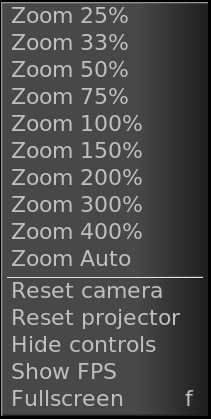
Right clicking anywhere in the video output brings up a menu with all the zoom levels and some other options. Selecting a percentage here resizes the window. If the video size is locked to the window size, the video changes size. If the video size is unlocked from the window size, the video stays the same size.
Selecting auto locks the video to the window size.
The reset camera and reset projector options center the camera and projector See COMPOSITING.
The Hide controls option hides everything except the video.
If video is unlocked from the window size, middle clicking and dragging anywhere in the video pans the point of view.
Hitting the + and - keys unlocks the video size from the window size & zooms in and out of the video output.
Underneath the video output are copies of many of the functions
available in the main window. In addition there is a
 zoom menu and a
  tally light.
Selecting a percentage in the zoom menu unlocks the video size from the window size. Selecting Auto locks the video size to the window size.
The zoom menu does not affect the window size.
The tally light turns red when rendering is happening. This is useful for knowing if the output is current.
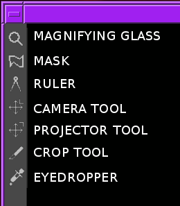
On the left of the video output is a toolbar specific to the compositor window. Select a tool to enable it. Select it again to disable it. To protect the video from changes, be sure all the tools are deselected. Here are the functions in the toolbar:
| • MAGNIFYING GLASS: | ||
| • MASKS TOOL: | ||
| • RULER: | ||
| • CAMERA: | ||
| • PROJECTOR: | ||
| • CROP TOOL: | ||
| • EYEDROPPER: | ||
Next: MASKS TOOL, Up: COMPOSITOR [Contents]
This zooms in and out of the compositor output without resizing the window. If the video output is currently locked to the size of the window, clicking in it with the magnifying glass unlocks it and creates scrollbars for navigation.
Left clicking in the video zooms in.
Ctrl clicking in the video zooms out.
Rotating the wheel on a wheel mouse zooms in and out.
Next: RULER, Previous: MAGNIFYING GLASS, Up: COMPOSITOR [Contents]

This brings up the mask editing tool See MASKS.
Next: CAMERA, Previous: MASKS TOOL, Up: COMPOSITOR [Contents]
The ruler shows pixel coordinates for the cursor & a line. Click drag in the video output to draw a line to measure. Click without dragging to hide the ruler line.
Always draw it Causes the ruler line to be drawn in all the other tools. This allows the ruler to be used to align camera & projector movements.
Next: PROJECTOR, Previous: RULER, Up: COMPOSITOR [Contents]

This brings up the camera editing tool See THE CAMERA AND PROJECTOR.
Next: CROP TOOL, Previous: CAMERA, Up: COMPOSITOR [Contents]

This brings up the projector editing tool See THE CAMERA AND PROJECTOR.
Next: EYEDROPPER, Previous: PROJECTOR, Up: COMPOSITOR [Contents]

This brings up the cropping tool See CROPPING.
Previous: CROP TOOL, Up: COMPOSITOR [Contents]

This brings up the eyedropper. The eyedropper detects whatever color is under it and stores it.
Click anywhere in the video output to select the color at that point.
radius Determines the size of the area that the eyedropper scans. The average of the area is used.
use maximum Uses the maximum values from the scanned area instead of the average.
The eyedropper value can be applied to many effects. Different effects handle the eyedropper differently. They usually have an option called use color picker to use the last scanned eyedropper color.
Next: RESOURCES, Previous: COMPOSITOR, Up: THE MAIN WINDOWS [Contents]
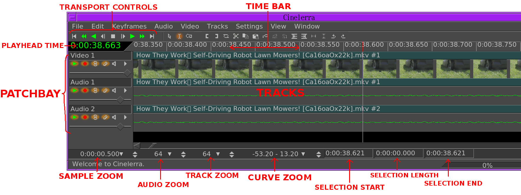
This contains the timeline and the entry point for all menu driven operations. The timeline consists of a vertical stack of tracks with horizontal representation of time. This defines the output of rendering operations and what is saved when you save files. Left of the tracks is the patchbay which contains options affecting each track.
Above the tracks is the time bar. Right click in the time bar to select a time format. The time format is used by all the clocks.
Under the Window menu you’ll find options affecting the main windows. default positions repositions all the windows to a 4 screen editing configuration. On dual headed displays, the default positions operation fills only one monitor with windows.
Next: SOUND LEVEL METERS, Previous: PROGRAM, Up: THE MAIN WINDOWS [Contents]
Effects, transitions, clips, and assets are accessed here. Most of the resources are inserted into the project by dragging them out of the resource window. Management of resource allocation is also performed here.
Next: OTHER WINDOWS, Previous: RESOURCES, Up: THE MAIN WINDOWS [Contents]
An additional window, the levels window can be brought up from the Window menu. The levels window displays the output audio levels after all mixing is done.
Sound level meters appear in many locations. They can be toggled in
the viewer and compositor windows with the  level
toggle. They appear in the patchbay when a track is expanded (See THE PATCHBAY.) They appear in the recording monitor when audio is being
recorded.
level
toggle. They appear in the patchbay when a track is expanded (See THE PATCHBAY.) They appear in the recording monitor when audio is being
recorded.
The sound levels in the levels window, compositor, and viewer correspond to the final output levels before they are clipped to the soundcard range. In the record monitor they are the input values from the sound card. In the patchbay they are the sound levels for each track after all effects are processed and before downmixing for the output.
Most of the time, audio levels have numerical markings in DB but in the patchbay there isn’t enough room.
The sound level is color coded as an extra means of determining the sound level. Even without numerical markings, the sound level color can distinguish between several ranges and overload. Look at the color codings in a meter with numerical markings to see what colors correspond to what sound level. Then for meters in the patchbay in expanded audio tracks, use the color codings to see if it’s overloading.
Be aware that sound levels in Cinelerra can go above 0DB. This allows not only seeing if a track is overloading but how much information is being lost by the overloading. Overloading by less than 3DB is usually acceptable. While overloading is treated as positive numbers in Cinelerra, it is clipped to 0 when sent to a sound card or file.
The visible range of the sound level meters is configurable in settings->preferences->interface (See INTERFACE.)
Previous: SOUND LEVEL METERS, Up: THE MAIN WINDOWS [Contents]
The Overlays window can be brought up from the Window menu. This is a quick way to toggle what is drawn in the timeline. Every option in the View menu is available here.
Next: NAVIGATING THE PROJECT, Previous: THE MAIN WINDOWS, Up: TOP [Contents]
| • SUPPORTED MEDIA FORMATS: | What formats Cinelerra can import and export | |
| • LOADING FILES: | Loading all types of files | |
| • LOADING THE BACKUP: | Recovering the session from before a crash | |
| • SAVING FILES: | Saving edit decision lists | |
| • RENDERING FILES: | Saving media files |
Next: LOADING FILES, Up: LOADING AND SAVING FILES [Contents]
Cinelerra reads most of the file formats found on the internet, with limited support for pro camera output. You may be able to load other formats not described here. Most of the decoding is done through ffmpeg, which entails writing a new API for every new codec. It tends to go a few years between codec updates so a lot of new codecs can be combined in a single API rewrite.
Most of the video rendering is now done through ffmpeg, using the Command Line file format. A few formats like Quicktime/MP4 & audio formats still come out better when they’re sent through their dedicated libraries.
Whether it’s a media format or an edit decision list affects what Cinelerra does with it. Edit decision lists replace the project settings. Formats which contain media but no edit decisions just add data to the tracks unless the Conform Project option is enabled in the load dialog.
If your project sample rate is 48khz and you load a sound file with 96khz, you’ll still be playing it at 48khz. If you load an EDL file at 96khz and the current project sample rate is 48khz, you’ll change it to 96khz.
Some file formats are very slow to display on the timeline. These usually have video which is highly compressed. Disable picon drawing for these files with the draw media toggle to speed up operations.
Track attributes
Supported file formats are currently:
| • COMMAND LINE ENCODER: | ||
| • QUICKTIME: | ||
| • MPEG-4 AUDIO: | ||
| • IMAGE SEQUENCES: | ||
| • STILL IMAGES: | ||
| • AVI: | ||
| • MPEG FILES CONTAINING VIDEO: | ||
| • DVD MOVIES: | ||
| • MPEG 1 AUDIO: | ||
| • OGG THEORA/VORBIS: | ||
| • EDIT DECISION LIST: |
Next: QUICKTIME, Up: SUPPORTED MEDIA FORMATS [Contents]
This writes the output through a pipe to a command line program, usually ffmpeg but it can also be /dev/null or netcat. Audio & video are supported. Different command lines can be used for encoding audio & video, then multiplexing them into a single file. There’s a GUI for presets & storing different command lines.
Someone could conceivably read video from Live video & write it to netcat to use the render operation as a live video processor.
The main use of command line encoding is GPU encoding through ffmpeg. A GPU encoding ffmpeg is not officially included in the Cinelerra distribution because of licensing restrictions, although there may or may not be an unofficial copy.
It officially has to be compiled from scratch & it’s very specific to the hardware. For nvidia, it needs nvenc support. There is a buried document showing how to build ffmpeg with hardware support on
https://docs.nvidia.com/video-technologies/video-codec-sdk/ffmpeg-with-nvidia-gpu/
We can build an ffmpeg to show you what works. In the ffmpeg directory, run
./configure –enable-pthreads –disable-ffplay –enable-nonfree –enable-gpl –enable-cuda-nvcc –enable-libnpp –nvccflags=-I/usr/local/cuda/include –extra-cflags=-I/usr/local/cuda/include –extra-ldflags=-L/usr/local/cuda/lib64
This also requires a working CUDA installation. Then run make.
The main encoding we’re interested in accelerating is video, so enable RENDER VIDEO TRACKS. Then go to the wrench icon. It has a number of presets. Highlight a preset & hit load to make it use the preset. If you make changes to the preset, hit save to overwrite it, otherwise the change will be applied to the current rendering job but not saved as a preset.
If you want to create a new preset, change the title before hitting save. If you screw up a preset that came with the program, delete the preset & restart the program. It’ll always recreate the default presets.
Ffmpeg HEVC VBR is a variable bitrate encoder for H.265. HEVC CBR is a constant bitrate encoder for H.265. In the command lines are the ffmpeg options for a fixed quantization factor or a fixed bitrate.
Finally, there is the ever important null encoder which just throws away the output. This is useful for benchmarking rendering.
The command line takes some formatting codes for the frame rate, frame size, & filename.
An important option is the color model. It most often should be YUV 420 planar.
The audio & video encoder have similar windows. The audio encoding takes a sample format instead of a color model. A very common error with ffmpeg is the dreaded "input contains (near) nan/+-inf" If you get this error, it means the audio encoder expects the samples in 1 format but Cinelerra is outputting another format. It usually happens when trying to enclode floating point. A safe setting is 24 bit linear, signed, non dithered, lo hi byte order.
The wrapper runs after the audio & video encoding is finished. An important option in the wrapper is deleting the temporaries. If the wrapper doesn’t work, you may not want to reencode everything to try again. In this case, you don’t want to delete the temporaries but want to run the wrapper on the command line a 2nd time.
Next: MPEG-4 AUDIO, Previous: COMMAND LINE ENCODER, Up: SUPPORTED MEDIA FORMATS [Contents]
Quicktime was not originally the standard for UNIX but we used it because it was well documented. It later became MP4. All of the Quicktime movies on the internet are compressed. Cinelerra doesn’t support most compressed Quicktime movies but does support some. If it crashes when loading a Quicktime movie, that means the format probably wasn’t supported.
NOTES ON QUICKTIME ENCODING
Here are some notes regarding making Quicktime movies in Cinelerra:
Quicktime is a wrapper for 2 codecs, a video codec and an audio codec. The video and audio codecs are picked separately. The preferred encoding for Quicktime output is MPEG-4 Video and MPEG-4 Audio. This format plays in the commercial players for Windows and has good compression quality. For better compression, use H-264 Video. Unfortunately H-264 decoding is so slow it can’t play very large frame sizes.
Cinelerra supports 2 nonstandard codecs: Dual MPEG-4 video and dual H.264 video. These won’t play in anything but Cinelerra and XMovie. They are designed for movies where the frames have been divided into 2 fields, each field displayed sequentially. The dual codecs interleave 2 video streams to improve efficiency without requiring major changes to the player.
Next: IMAGE SEQUENCES, Previous: QUICKTIME, Up: SUPPORTED MEDIA FORMATS [Contents]
This is the same as Quicktime with MPEG-4 Audio as the audio codec.
Next: STILL IMAGES, Previous: MPEG-4 AUDIO, Up: SUPPORTED MEDIA FORMATS [Contents]
Rendering an image sequence is not the same as rendering a single image. When rendering an image sequence Cinelerra generates a table of contents file for the image sequence and makes a different image file for every timeline position. The table of contents can be loaded instead of the individual images to get better performance. To learn more about the different image formats supported in an image sequence, read about still images.
Next: AVI, Previous: IMAGE SEQUENCES, Up: SUPPORTED MEDIA FORMATS [Contents]
Rendering a single image causes the image file to be overwritten for every timeline position. No table of contents is created. When loaded, the image takes up one frame in length and doesn’t change the project attributes.
Several still image formats not normally found in other programs are described here.
| • OPEN EXR IMAGES: | ||
| • RAW DIGITAL CAMERA IMAGES: |
Next: RAW DIGITAL CAMERA IMAGES, Up: STILL IMAGES [Contents]
You may not know about Open EXR. This format stores floating point RGB images. It also supports a small amount of compression. Projects which render to EXR should be in a floating point color model to take advantage of it See SETTING PROJECT ATTRIBUTES. Several compression options are available for EXR.
Select Use Alpha if the project colormodel has an alpha channel and you want to retain it in the file. Otherwise the primary colors are multiplied by the alpha channel.
Previous: OPEN EXR IMAGES, Up: STILL IMAGES [Contents]
RAW digital camera images are a special kind of image file which Cinelerra only imports. These must be processed in a floating point color space once they are on the timeline. Raw images from Canon cameras are the only ones tested. They need to have the Linearize effect applied to correct gamma. Because raw images take a long time to interpolate, they are usually viewed first in a proxy file and then touched up.
First apply the Linearize effect to a track of raw images and set it to automatic with 0.6 gamma. Then render the timeline to a Quicktime JPEG file. Append the Quicktime JPEG file in a new track and disable playback of the old track. Now the gamma corrected copy of each raw image can be previewed relatively fast in the same timeline position as the original image.
Next: MPEG FILES CONTAINING VIDEO, Previous: STILL IMAGES, Up: SUPPORTED MEDIA FORMATS [Contents]
AVI with assorted audio and video codecs. Because AVI is so fragmented, your luck will vary.
Next: DVD MOVIES, Previous: AVI, Up: SUPPORTED MEDIA FORMATS [Contents]
MPEG files containing video can be loaded directly into Cinelerra. If the file is supported, a table of contents is built. If the file is unsupported, it usually crashes or shows very short tracks. Unfortunately, this method of loading MPEG files isn’t good enough if you intend to use the files in a renderfarm.
To use MPEG files in a renderfarm you need to run mpeg3toc to generate a table of contents for the file, then load the table of contents. Mpeg3toc needs the absolute path of the MPEG file. If you don’t use an absolute path, it assumes the MPEG file is in the same directory that Cinelerra is run from.
MPEG streams are structured into multiple tracks. Each track can be video or audio. Each audio track can have 1-6 channels. Cinelerra converts each channel of audio into a track.
NOTES ON MPEG VIDEO ENCODING
MPEG video encoding is done separately from MPEG audio encoding. In MPEG video there are 2 colormodels. The YUV 4:2:0 colormodel is encoded by a highly optimized version of mpeg2enc with presets for standard consumer electronics. In the process of optimizing mpeg2enc, they got rid of YUV 4:2:2 encoding. The YUV 4:2:2 colormodel is encoded by a less optimized version of mpeg2enc.
YUV 4:2:2 encoding was kept around because the NTSC version of DV video loses too much quality when transferred to YUV 4:2:0. This DV video must be transferred to YUV 4:2:2.
When encoding YUV 4:2:0, the bitrate parameter changes meaning depending on whether the bitrate or quantization is fixed. If the bitrate is fixed, it’s the target bitrate. If the quantization is fixed, it’s the maximum bitrate allowed. This is a quirk of the mpeg2enc version.
Next: MPEG 1 AUDIO, Previous: MPEG FILES CONTAINING VIDEO, Up: SUPPORTED MEDIA FORMATS [Contents]
DVD’s are spit into a number of programs, each identified by a unique IFO file. If you want to load a DVD, find the corresponding IFO file for the program of interest. Load the IFO file directly and a table of contents will be built. Alternatively for renderfarm usage, a table of contents can be created separately.
Run
mpeg3toc -v /cdrom/video_ts/vts_01_0.ifo dvd.toc
or something similar. Then load dvd.toc.
Next: OGG THEORA/VORBIS, Previous: DVD MOVIES, Up: SUPPORTED MEDIA FORMATS [Contents]
These are .mp2 and .mp3 files. If fixed bitrate, they can be loaded directly with no table of contents. Variable bitrate streams need to have a table of contents created with mpeg3toc.
Next: EDIT DECISION LIST, Previous: MPEG 1 AUDIO, Up: SUPPORTED MEDIA FORMATS [Contents]
The OGG format is an antiquated but supposedly unpatented way of compressing audio and video. The quality isn’t as good as H.264 or MPEG-4 Audio. In reality, anyone with enough money and desire can find a patent violation so the justification for OGG is questionable.
Previous: OGG THEORA/VORBIS, Up: SUPPORTED MEDIA FORMATS [Contents]
Edit decision lists are generated by Cinelerra for storing projects. They end in .xml. They change project attributes when loaded.
Because edit decision lists consist of text, they can be edited in a text editor.
Next: LOADING THE BACKUP, Previous: SUPPORTED MEDIA FORMATS, Up: LOADING AND SAVING FILES [Contents]
All data that you work with in Cinelerra is acquired either by recording from a device or by loading from disk. This section describes loading.
The loading and playing of files is just as you would expect. Just go to file->Load, select a file for loading, and hit ok. Hit the forward play button and it should start playing, regardless of whether a progress bar has popped up.
Another way to load files is to pass the filenames as arguments on the command line. This creates new tracks for every file and starts the program with all the arguments loaded.
If the file is a still image, the project’s attributes are not changed and the first frame of the track becomes the image. If the file has audio, Cinelerra may build an index file for it to speed up drawing. You can edit and play the file while the index file is being built.
| • LOAD MODE: | ||
| • CONFORM PROJECT: | ||
| • LOADING MULTIPLE FILES: | ||
| • FILE PREVIEWS: |
Next: CONFORM PROJECT, Up: LOADING FILES [Contents]
Usually three things happen when you load a file. First the existing project is cleared from the screen, second the project’s attributes are changed to match the file’s, and finally the new file’s tracks are created in the timeline.
But Cinelerra lets you change what happens when you load a file.
In the file selection box there is a range of options for load mode. Each of these options loads the file a different way. The load mode is a recurring theme in many of Cinelerra’s functions. A lot of steps that would normally entail editing operations on the timeline can be automated by setting the right load mode.
If you load files by passing command line arguments to Cinelerra, the files are always loaded with the Replace current project mode.


All tracks in the current project are deleted and new tracks are created to match the source. Project attributes are only changed when loading XML. If multiple files are selected it adds new tracks for every file.

Same as replace current project except if multiple files are selected it concatenates the tracks of every file after the first.

The current project is not deleted and new tracks are created for the source.

The current project is not deleted and new files are concatenated to the existing tracks.

The file is pasted in like a normal paste operation.

The timeline is unchanged and new resources are created in the Resource Window.

If the file is an EDL, the output of the EDL is pasted in like a media file. Nested EDLs have 1 video track & a number of audio tracks corresponding to the number of output channels. They allow larger sequences composed of many smaller sequences, transitions to be applied to the output of another EDL, & global processing on the output of an EDL without having to manipulate each track.
Next: LOADING MULTIPLE FILES, Previous: LOAD MODE, Up: LOADING FILES [Contents]
This causes the project settings to be changed to match the 1st loaded media file. Video size, frame rate, sample rate, but not the number of channels are changed. This only happens in the load modes which replace the current project.
Next: FILE PREVIEWS, Previous: CONFORM PROJECT, Up: LOADING FILES [Contents]
In the file selection box go to the list of files. Select a file. Go to another file and select it while holding down CTRL. This selects one additional file. Go to another file and select it while holding down SHIFT. This selects every intervening file. This behavior is available in most every list box.
Select a bunch of mp3 files and Replace current project and concatenate tracks in the load mode to create a song playlist.
Previous: LOADING MULTIPLE FILES, Up: LOADING FILES [Contents]
File previews are shown only if the show preview  toggle is enabled. Highlighting a file causes it to try to load a
preview. There are certain rules for which files it can preview. There
are limits to the frame size, file size of an image file. Certain EDL’s
can be previewed, usually limited to a single video track with no
effects & only 1 asset. The reason an EDL can’t be previewed will
usually be printed on the command line.
toggle is enabled. Highlighting a file causes it to try to load a
preview. There are certain rules for which files it can preview. There
are limits to the frame size, file size of an image file. Certain EDL’s
can be previewed, usually limited to a single video track with no
effects & only 1 asset. The reason an EDL can’t be previewed will
usually be printed on the command line.
Next: SAVING FILES, Previous: LOADING FILES, Up: LOADING AND SAVING FILES [Contents]
There is one special XML file on disk at all times. After every editing operation Cinelerra saves the current project to a backup in $HOME/.bcast/backup.xml. In the event of a crash go to file->load backup to load the backup. It is important after a crash to reboot Cinelerra without performing any editing operations. Loading the backup should be the first operation or you’ll overwrite the backup.
Next: RENDERING FILES, Previous: LOADING THE BACKUP, Up: LOADING AND SAVING FILES [Contents]
When Cinelerra saves a file it saves an edit decision list of the current project but doesn’t save any media. Go to File->save as.... Select a file to overwrite or enter a new file. Cinelerra automatically concatenates .xml to the filename if no .xml extension is given.
The saved file contains all the project settings and locations of every edit but instead of media it contains pointers to the original media files on disk.
For each media file the XML file stores either an absolute path or just the relative path. If the media is in the same directory as the XML file a relative path is saved. If it’s in a different directory an absolute path is saved.
In order to move XML files around without breaking the media linkages you either need to keep the media in the same directory as XML file forever or save the XML file in a different directory than the media and not move the media ever again.
If you want to create an audio playlist and burn it on CD-ROM, save the XML file in the same directory as the audio files and burn the entire directory. This keeps the media paths relative.
XML files are useful for saving the current state before going to sleep and saving audio playlists but they’re limited in that they’re specific to Cinelerra. You can’t play XML files in a dedicated movie player. Realtime effects in an XML file have to be resynthesized every time you play it back. The XML file also requires you to maintain copies of all the source assets on hard drives, which can take up space and cost a lot of electricity to spin. For a more persistent storage of the output there’s rendering.
Previous: SAVING FILES, Up: LOADING AND SAVING FILES [Contents]
Rendering takes a section of the timeline, performs all the editing, effects and compositing, and stores it in a pure movie file. You can then delete all the source assets, play the rendered file in a movie player, or bring it back into Cinelerra for more editing. It’s very difficult to retouch any editing decisions in the pure movie file, however, so keep the original assets and XML file around several days after you render it.
All rendering operations are based on a region of the timeline to be rendered. You need to define this region on the timeline. The navigation section describes methods of defining regions. See NAVIGATING THE PROJECT. The rendering functions define the region based on a set of rules. When a region is highlighted or in/out points are set, the affected region is rendered. When no region is highlighted, everything after the insertion point is rendered. Merely by positioning the insertion point at the beginning of a track and unsetting all in/out points, the entire track is rendered.
| • SINGLE FILE RENDERING: | Rendering a single file | |
| • BATCH RENDERING: | Rendering several files unattended | |
| • THE RENDER FARM: | Rendering using many computers | |
| • RENDERING WITHOUT A GUI: | Rendering from the command line without a GUI |
Next: BATCH RENDERING, Up: RENDERING FILES [Contents]
The fastest way to get media to disk is to use the single file rendering function.
Go to File->render to bring up the render dialog. Select the
magnifying glass to bring up a file selection dialog. This determines
the filename to write the rendered file to and the encoding parameters.
In the render dialog select a format from the File Format menu. The format of the file determines whether you can render audio or video or both. Select the Render audio tracks toggle to generate audio tracks and Render video tracks to generate video tracks.
Select the wrench next to each toggle to set compression
parameters. If the file format can’t store audio or video the
compression parameters will be blank. If Render audio tracks or
Render video tracks is selected and the file format doesn’t
support it, trying to render will pop up an error.
The Create new file at each label option causes a new file to be created when every label in the timeline is encountered. This is useful for dividing long audio recordings into individual tracks. When using the renderfarm, Create new file at each label causes one renderfarm job to be created at every label instead of using the internal load balancing algorithm to space jobs.
When Create new file at each label is selected, a new filename is created for every output file. If the filename given in the render dialog has a 2 digit number in it, the 2 digit number is overwritten with a different incremental number for every output file. If no 2 digit number is given, Cinelerra automatically concatenates a number to the end of the given filename for every output file.
In the filename /hmov/track01.wav the 01 would be overwritten for every output file. The filename /hmov/track.wav; however, would become /hmov/track.wav001 and so on and so forth. Filename regeneration is only used when either renderfarm mode is active or creating new files for every label is active.
Finally the render dialog lets you select an insertion mode. The insertion modes are the same as with loading files. In this case if you select insert nothing the file will be written out to disk without changing the current project. For other insertion strategies be sure to prepare the timeline to have the output inserted at the right position before the rendering operation is finished. See EDITING. Editing describes how to cause output to be inserted at the right position.
It should be noted that even if you only have audio or only have video rendered, a paste load mode will behave like a normal paste operation, erasing any selected region of the timeline and pasting just the data that was rendered. If you render only audio and have some video tracks armed, the video tracks will get truncated while the audio output is pasted into the audio tracks.
Next: THE RENDER FARM, Previous: SINGLE FILE RENDERING, Up: RENDERING FILES [Contents]
If you want to render many projects to media files without having to repeatedly attend to the Render dialog, batch rendering is the function to use. In this function, you specify many EDL files to render and the unique output files for each. Then Cinelerra loads each EDL file and renders it automatically, without any user intervention. Each EDL file and its output to be rendered is called a batch. This allows a huge amount of media to be processed and greatly increases the value of an expensive computer.
The first thing to do when preparing to do batch rendering is define projects to be rendered. The batch renderer requires a separate EDL file for every batch to be rendered. Set up a project and define the region to be rendered either by highlighting it, setting in/out points around it, or positioning the insertion point before it. Then save the project as an EDL. Define as many projects as needed this way. The batch renderer takes the active region from the EDL file for rendering.
With all the EDL files prepared with active regions, go to File->batch render. This brings up the batch rendering dialog. The interface for batch rendering is a bit more complex than for single file rendering.
A list of batches must be defined before starting a batch rendering operation. The table of batches appears on the bottom of the batch render dialog and is called batches to render. Above this are the configuration parameters for a single batch.
Set the output path, file format, Audio, Video, and Create new file at each label parameters as if it was a single file. These parameters apply to only one batch. In addition to the standard rendering parameters, you must select the source EDL to use in the batch. Do this by setting the EDL path.
If the batches to render list is empty or nothing is highlighted, click New to create a new batch. The new batch will contain all the parameters you just set.
Repeatedly press the New button to create more batches with the same parameters. Highlight any batch and edit the configuration on the top of the batch render window. The highlighted batch is always synchronized to the information displayed.
Click and drag batches to change the order in which they’re rendered. Hit delete to permanently remove the highlighted batch.
In the list box is a column which enables or disables the batch. This way batches can be skipped without being deleted. Click on the Enabled column in the list box to enable or disable a batch. If it is checked, the batch is rendered. If it is blank, the batch is skipped.
The other columns in the batch list are informative.
To start rendering from the first enabled batch, hit Start.
Once rendering, the main window shows the progress of the batch. Once the batch finishes, the elapsed column in the batch list is updated and the next batch is rendered until all the enabled batches are finished. The currently rendering batch is always highlighted red.
To stop rendering before the batches are finished without closing the batch render dialog, hit Stop.
To stop rendering before the batches are finished and close the batch render dialog, hit Cancel.
To exit the batch render dialog whether or not anything is being rendered, hit Cancel.
Next: RENDERING WITHOUT A GUI, Previous: BATCH RENDERING, Up: RENDERING FILES [Contents]
When bicubic interpolation and HDTV was first done on Cinelerra, the time needed to produce the simplest output became unbearable even on the fastest dual 1.7Ghz Xeon of the time. Renderfarm support even in the simplest form brings HDTV times back in line with SD while making SD faster than realtime.
While the renderfarm interface isn’t spectacular, it’s simple enough to use inside an editing suite with less than a dozen nodes without going through the same amount of hassle you would with a several hundred node farm. Renderfarm is invoked transparently for all file->render operations when it is enabled in the preferences.
Cinelerra divides the selected region of the timeline into a certain number of jobs which are then dispatched to the different nodes depending on the load balance. The nodes process the jobs and write their output to individual files on the filesystem. The output files are not concatenated. It’s important for all the nodes to have access to the same filesystem on the same mount point for assets.
If a node can’t access an input asset it’ll display error messages to its console but probably not die. If it can’t access an output asset it’ll cause the rendering to abort.
It should be noted that in the render dialog, the Create new file at each label option causes a new renderfarm job to be created at each label instead of by the load balancer. If this option is selected when no labels exist, only one job will be created.
A Cinelerra renderfarm is organized into a master node and any number of slave nodes. The master node is the computer which is running the GUI. The slave nodes are anywhere else on the network and are run from the command line. Run a slave node from the command line with
cinelerra -d
That is the simplest configuration. Type cinelerra -h to see more options. The default port number may be overridden by passing a port number after the -d.
Most of the time you’ll want to bring in the rendered output and fine tune the timing on the timeline. Also some file formats like MPEG can’t be direct copied. Because of this, the jobs are left in individual files.
You can load these by creating a new track and specifying concatenate to existing tracks in the load dialog. Files which support direct copy can be concatenated into a single file by rendering to the same file format with renderfarm disabled. Also to get direct copy, the track dimensions, output dimensions, and asset dimensions must be equal.
MPEG files or files which don’t support direct copy have to be concatenated with a command line utility. MPEG files can be concatenated with cat.
Configuration of the renderfarm is described in the configuration chapter See RENDERFARM. The slave nodes traditionally read and write data to a common filesystem over a network, thus they don’t need hard drives.
Ideally all the nodes on the renderfarm have similar CPU performance. Cinelerra load balances on a first come first serve basis. If the last segment is dispatched to the slowest node, all the fastest nodes may end up waiting for the slowest node to finish while they themselves could have rendered it faster.
Previous: THE RENDER FARM, Up: RENDERING FILES [Contents]
Cinelerra can be run without a GUI. The command line rendering facility consists of a way to load the current set of batch rendering jobs and process them. This is useful if you’re planning on crashing X repeatedly or want to do rendering on the other side of a low bandwidth network. You might have access to a supercomputer in China but still be stuck in Amerika, exhiled you might say. A command line interface is ideal for this.
To perform rendering from the command line, first run Cinelerra in graphical mode. Go to file->batch render. Create the batches you intend to render in the batch window and close the window. This saves the batches in a file. Set up the desired renderfarm attributes in settings->preferences and exit Cinelerra. These settings are used the next time command line rendering is used.
On the command line run
cinelerra -r
to processes the current batch jobs without a GUI. Setting up all the parameters for this operation is hard. That’s why the command line aborts if any output files already exist.
For specifying an alternative preferences file, there’s the -c option.
For loading an alternative batch file, the -r option takes a filename.
Running cinelerra -h shows a description of all the options. Attempting to use anything but the default files is very involved so it has never been tested.
Next: EDITING, Previous: LOADING AND SAVING FILES, Up: TOP [Contents]
The thing you want to do most of the time is get to a certain time and place in the media. Internally the media is organized into tracks. Each track extends across time. Navigation involves both getting to a track and getting to a certain time in the track.
| • NAVIGATING THE PROGRAM WINDOW: | ||
| • NAVIGATING THE VIEWER AND COMPOSITOR: | ||
| • NAVIGATING THE RESOURCES: | ||
| • USING THE TRANSPORT CONTROLS: | ||
| • USING BACKGROUND RENDERING: |
The program window contains many features for navigation and displays the timeline as it is structured in memory: tracks stacked vertically and extending across time horizontal. The horizontal scroll bar allows you to scan across time. The vertical scroll bar allows you to scan across tracks.
Below the timeline you’ll find the zoom panel. The zoom panel contains values for sample zoom, amplitude, track zoom, and curve zoom. These values in addition to the scrollbars are the main tools for positioning the timeline.

Changing the sample zoom causes the amount of time visible to change. If your mouse has a wheel and it works in X11 go over the tumblers and use the wheel to zoom in and out. The sample zoom is in units of samples per pixel. It does this so different windows of different sizes can easily show the same zoom level. Past attempts to show the width of the window in time units were more difficult to navigate.
The amplitude only affects audio. It determines how big the waveform is if the waveform is drawn.
The track zoom affects all tracks. It determines the height of each track. If you change the track zoom the amplitude zoom compensates so audio waveforms look proportional.
The curve zoom affects the curves in all the tracks. It
determines the amplitude and offset of the curves. The tumbler affects
curve amplitude but the only way to change curve offset is to use the
fit curves button. 
In addition to the graphical tools, you’ll probably more often use the keyboard to navigate. Use PAGE UP and PAGE DOWN to scroll up and down the tracks.
Use the LEFT and RIGHT arrows to move across time in small increments. You’ll often need to scroll beyond the end of the timeline but scrollbars won’t let you do it. Instead use the RIGHT arrow to scroll past the end of timeline.
Use the HOME and END keys to instantly go to the beginning or end of the timeline. In I-beam mode, hold down shift while pressing HOME or END to select the region of the timeline between the insertion point and the key pressed.
Use the UP and DOWN arrows to change the sample zoom by a power of 2.
CTRL-UP and CTRL-DOWN cause the amplitude zoom to change.
CTRL-PGUP and CTRL-PGDOWN cause the track zoom to change.
ALT-UP and ALT-DOWN cause the curve amplitude to change.
| • THE INSERTION POINT: | ||
| • THE IN/OUT POINTS: | ||
| • USING LABELS IN THE PROGRAM WINDOW: |
Next: THE IN/OUT POINTS, Up: NAVIGATING THE PROGRAM WINDOW [Contents]
By default you’ll see a flashing insertion point in the program window the first time you boot it up. This is where new media is pasted onto the timeline. It’s also the starting point of all playback operations. When rendering, it defines the region of the timeline to be rendered.
The insertion point is normally moved by clicking inside the timebar. Any region of the timebar not obscured by labels and in/out points is a hotspot for repositioning the insertion point.

The main timebar
The insertion point also can be moved by clicking in the timeline itself, but not always. The insertion point has two modes of operation:
The mode of operation is determined by selecting the arrow or the i-beam in the buttonbar.

The editing mode buttons
If the arrow is highlighted it enables drag and drop mode. In drag and drop mode, clicking in the timeline doesn’t reposition the insertion point. Instead it selects an entire edit. Dragging in the timeline repositions the edit, snapping it to other edit boundaries. This is normally useful for reordering audio playlists and moving effects around.
If the i-beam is highlighted it enables cut and paste mode. In cut and paste mode clicking in the timeline repositions the insertion point. Dragging in the timeline highlights a region. The highlighted region becomes the playback range during the next playback operation, the rendered range during the next render operation, and the region affected by cut and paste operations.
Shift-clicking in the timeline extends the highlighted region.
Double-clicking in the timeline selects the entire edit the cursor is over.
It should be noted that when moving the insertion point and selecting regions, the positions are either aligned to frames or aligned to samples. When editing video you’ll want to align to frames. When editing audio you’ll want to align to samples. This is set in settings->align cursor on frames.
If the highlighted region is the region affected by cut and paste operations, how do I cut and paste in drag and drop mode? In this case you need to set in/out points to define an affected region.
Next: USING LABELS IN THE PROGRAM WINDOW, Previous: THE INSERTION POINT, Up: NAVIGATING THE PROGRAM WINDOW [Contents]
In both editing modes you can set in/out points. The in/out points define the affected region. In drag and drop mode they are the only way to define an affected region. In both cut and paste mode and drag and drop mode the highlighted area overrides the in/out points. If a highlighted area and in/out points are set, the highlighted area is affected by editing operations and the in/out points are ignored. If no region is highlighted, the in/out points are used.
Normally, in/out points do not affect the playback region. Only if you hold down CTRL while issuing a playback command do the in/out points determine the playback region.
To set in/out points go to the timebar and position the insertion point
somewhere. Hit the  in point button. Go
to a position after the in point and hit the
in point button. Go
to a position after the in point and hit the  out point button.

Timebar with in/out points set.
Select either the in point or the out point and the insertion point jumps to that location. After selecting an in point, if you hit the in point button the in point will be deleted. After selecting an out point, if you hit the out point button the out point will be deleted.
If you select a region somewhere else while in/out points already exist, the existing points will be repositioned when you hit the in/out buttons.
Shift-clicking on an in/out point extends the highlighted region to that point.
Instead of using the button bar you can use the [ and ] keys to toggle in/out points.
The insertion point and the in/out points allow you to define an affected region but they don’t let you jump to exact points on the timeline very easily. For this purpose there are labels.
Previous: THE IN/OUT POINTS, Up: NAVIGATING THE PROGRAM WINDOW [Contents]
Labels are an easy way to set exact locations on the timeline you want
to jump to. When you position the insertion point somewhere and hit
the  label button a new label appears on the
timeline.
label button a new label appears on the
timeline.

Timebar with a label on it
No matter what the zoom settings are, clicking on the label positions the insertion point exactly where you set it. Hitting the label button again when a label is selected deletes it.
Shift-clicking on a label extends the highlighted region.
Double-clicking between two labels highlights the region between the labels.
Hitting the l key has the same effect as the label button.
If you hit the label button when a region is highlighted, two labels are toggled at each end of the highlighted region. If one end already has a label, then the existing label is deleted and a label is created at the opposite end.
Labels can reposition the insertion point when they are selected but
they can also be traversed with the  label
traversal buttons. When a label is out of view, the label traversal
buttons reposition the timeline so the label is visible. There are
keyboard shortcuts for label traversal, too.
label
traversal buttons. When a label is out of view, the label traversal
buttons reposition the timeline so the label is visible. There are
keyboard shortcuts for label traversal, too.
CTRL-LEFT repositions the insertion point on the previous label.
CTRL-RIGHT repositions the insertion point on the next label.
With label traversal you can quickly seek back and forth on the timeline but you can also select regions.
SHIFT-CTRL-LEFT extends the highlighted region to the previous label.
SHIFT-CTRL-RIGHT extends the highlighted region to the next label.
Manually hitting the label button or l key over and over again to delete a series of labels can get tedious. For deleting a set of labels, first highlight a region and second use the Edit->Clear labels function. If in/out points exist, the labels between the in/out points are cleared and the highlighted region ignored.
Next: NAVIGATING THE RESOURCES, Previous: NAVIGATING THE PROGRAM WINDOW, Up: NAVIGATING THE PROJECT [Contents]
The navigation features of the Viewer and Compositor behave very similarly. Each has a timebar and slider below the video output. The timebar and slider are critical for navigation.

The timebar represents the entire time covered by the program. When you define labels and in/out points it defines those, too. Finally the timebar defines a region known as the preview region.
The preview region is the region of the timeline which the slider effects. The slider only covers the time covered by the preview region. By using a preview region inside the entire program and using the slider inside the preview region you can quickly and precisely seek in the compositor and viewer.
When you replace the current project with a file the preview region automatically resizes to cover the entire file. When you append data or change the size of the current project, the preview region stays the same size and shrinks. Therefore, you need to resize the preview region.
Load a file and then slide around it using the compositor slider. The insertion point in the main window follows the compositor. Move the pointer over the compositor’s timebar until it turns into a left resize pointer. The click and drag right. The preview region should have changed and the slider resized proportionally.
Go to the right of the timebar until a right resize pointer appears. Drag left so the preview region shrinks.
Go to the center of the preview region in the timebar and drag it around to convince yourself if can be moved.

Preview region in compositor
If you go to the slider and slide it around with the preview region shrunk, you’ll see the slider only affects the preview region. The timebar and slider in the viewer window work exactly the same.
Labels and in/out points are fully supported in the viewer and compositor. The only difference between the viewer and compositor is the compositor reflects the state of the program while the viewer reflects the state of a clip but not the program.
When you hit the label button in the compositor, the label appears both in the compositor timebar and the program timebar.
When you select a label or in/out point in the compositor, the program window jumps to that position.

Labels and in/out points in the viewer.
In the viewer and compositor, labels and in/out points are displayed in the timebar. Instead of displaying just a region of the program, the timebar displays the entire program here.
Like the Program window, the Compositor has a zoom capability. First, the pulldown menu on the bottom of the compositor window has a number of zoom options. When set to Auto the video is zoomed to match the compositor window size as closely as possible. When set to any other percentage, the video is zoomed a power of 2 and scrollbars can be used to scroll around the output. When the video is zoomed bigger than the window size, not only do scrollbars scan around it but middle mouse button dragging in the video output scans around it. This is exactly when The Gimp does.
Furthermore, the zoom toggle causes the Compositor
window to enter zoom mode. In zoom mode, clicking in the video output
zooms in while ctrl-clicking in the video output zooms out. If
you have a wheel mouse, rotating the wheel zooms in or out too.
Zooming in or out with the zoom tool does not change the rendered output, mind you. It’s merely for scrutinizing video or fitting it in the desktop.
Next: USING THE TRANSPORT CONTROLS, Previous: NAVIGATING THE VIEWER AND COMPOSITOR, Up: NAVIGATING THE PROJECT [Contents]
The resource window is divided into two areas. One area lists folders and another area lists folder contents. Going into the folder list and clicking on a folder updates the contents area with the contents of that folder.
The folder and contents can be displayed as icons or text.
Right clicking in the folder or contents area brings up a menu containing formatting options. Select Display text to display a text listing. Select Sort items to sort the contents of the folder alphabetically.
Next: USING BACKGROUND RENDERING, Previous: NAVIGATING THE RESOURCES, Up: NAVIGATING THE PROJECT [Contents]
Transport controls navigate relative to the current playhead position, while playing back. Each of the Viewer, Compositor, and Program windows has a transport panel. The Compositor & Program window control playback in the compositor window.
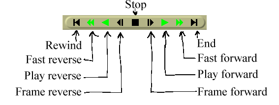
The transport panel.
More powerful control of the transport is provided by the keyboard than the graphical interface. For each of the operations it performs, the starting position is the position of the insertion point in the Program window and the slider in the Compositor window. The ending position is either the end or start of the timeline or the end or start of the selected region if there is one.
The orientation of the end or start depends on the direction of playback. If it’s forward the end position is the end of the selected region. If it’s backward the end position is the start of the selected region.
The insertion point moves to track playback. When playback stops, the insertion point stays where playback stopped. Thus, by playing back you change the position of the insertion point.
The keyboard interface is usually the fastest and has more speeds. The transport keys are arranged in a sideways T on the number pad.
Hitting any key on the keyboard twice pauses it & discards the playback range defined by the previous selection.
When using frame advance functions the behavior may seem odd. If you frame advance forward and then frame advance backward, the displayed frame doesn’t change. This is because the playback position isn’t the frame but the time between two frames. The rendered frame is the area that the playback position crosses. When you increment the time between two frames by one and decrement it by one, you cross the same frame both times and so the same frame is displayed.
Holding down CTRL when issuing any of the transport commands causes the starting point to be the in point if playing forward and the out point if playing backward. If playing forward, the out point becomes the ending point and if playing backward, the in point becomes the ending point. If no in/out points are specified, the behavior falls back to using the insertion point and selection boundaries as the starting and ending points.
Previous: USING THE TRANSPORT CONTROLS, Up: NAVIGATING THE PROJECT [Contents]
Background rendering allows impossibly slow effects to play back in realtime shortly after the effect is pasted in the timeline. It continuously renders temporary output. When renderfarm is enabled, background rendering uses the renderfarm continuously. This way, any size video can be seen in realtime merely by creating a fast enough network with enough nodes.
Background rendering is enabled in settings->preferences->performance. It has one interactive function: settings->set background render. This sets the point where background rendering begins to where the in point is. If any video exists, a red bar appears in the time bar showing what has been background rendered.
It’s often useful to insert an effect or a transition and then select settings->set background render right before the effect to preview it in full framerates.
Next: GENERAL EFFECT USAGE, Previous: NAVIGATING THE PROJECT, Up: TOP [Contents]
Editing comprises both the time domain and the track domain. Since the timeline consists of a stack of tracks, you need to worry about how to sort and create tracks in addition to what time certain media appears on a track.
In the time domain, Cinelerra offers many ways to approach the editing process. The three main methods are two screen editing, drag and drop editing, and cut and paste editing.
There are several concepts Cinelerra uses when editing which apply to all the methods. The timeline is where all editing decisions are represented. This is a stack of tracks in the center of the main window. It can be scrolled up, down, left and right with the scrollbars on the right and bottom of it. It can also be scrolled up and down with a mouse wheel.
The active region is the range of time which is affected by editing commands on the timeline. The active region is determined first by the presence of in/out points in the timeline. If those don’t exist the highlighted region is used. If no highlighted region exists the insertion point is used as the start of the active region. Some commands treat all the space to the right of the insertion point as active, like Render, while others treat the active length as 0 if no end point for the active region is defined.
Finally, editing decisions never affect source material. This is non destructive editing and it became popular with audio because it was much faster than if you had to copy all the media affected by an edit. Editing only affects pointers to source material, so if you want to have a media file at the end of your editing session which represents the editing decisions, you need to render it. See RENDERING FILES.
Every track on the timeline has a set of attributes on the left, the most important of which is the arm track attribute.
| • THE PATCHBAY: | Enabling different features on different tracks | |
| • NUDGING TRACKS: | Move entire tracks horizontally | |
| • PANNING TRACKS: | Changing the audio output channels | |
| • AUTOMATIC TRACK PANNING: | Panning tracks to common speaker arrangements | |
| • STANDARD AUDIO MAPPINGS: | Making audio panning that works on other players. | |
| • MANIPULATING TRACKS: | Moving whole tracks around | |
| • TWO SCREEN EDITING: | Using two video windows to edit | |
| • DRAG AND DROP EDITING: | Dragging objects to edit | |
| • DRAGGING EDITS: | Moving edits by dragging | |
| • SPLITTING & JOINING EDITS: | Create more edits for dragging | |
| • CUT AND PASTE EDITING: | Editing media like text | |
| • TRIMMING: | Changing in and out points | |
| • THE EDIT INFO DIALOG: | Hacking the EDL fields | |
| • EDIT MENU TOOLS: | Commands in the edit menu |
Next: NUDGING TRACKS, Up: EDITING [Contents]
On the left of the timeline is a region affectionately known as the patchbay. The patchbay enables features specific to each track. All tracks have a text area for naming the track.
All tracks have an expander  for viewing
more options and for viewing the effects on the track. Click on the
expander to expand or collapse the track. If it’s pointing sideways,
the track is collapsed. If it’s pointing down, the track is expanded.
The effects appear below the media for the track if they exist.
for viewing
more options and for viewing the effects on the track. Click on the
expander to expand or collapse the track. If it’s pointing sideways,
the track is collapsed. If it’s pointing down, the track is expanded.
The effects appear below the media for the track if they exist.
All tracks have the following row of toggles for several features.
Track attributes
If the toggle is colored, it is enabled. If the toggle is the background color of most of the windows, it is disabled. Click on the toggle to enable or disable the feature. Several mouse operations speed up the configuration of several tracks at a time.
Click on an attribute and drag across adjacent tracks to copy the same attribute to those tracks.
Hold down shift while clicking a track’s attribute to enable the attribute in the current track and toggle the attribute in all the other tracks.
Hold down shift while clicking an attribute. Click until all the tracks except the selected one are disabled. Then drag the cursor over the adjacent track to enable the attribute in the adjacent track.
The other attributes affect the output of the track.
In addition to restricting editing operations, the armed tracks in combination with the active region determine where material is inserted when loading files. If the files are loaded with one of the insertion strategies which doesn’t delete the existing project, the armed tracks will be used as destination tracks.
Press Tab while the cursor is anywhere over a track to toggle the track arming status.
Press Shift-Tab while the cursor is over a track to toggle the arming status of every other track.
Hold down shift and drag a fader to center it on 0.
Next: PANNING TRACKS, Previous: THE PATCHBAY, Up: EDITING [Contents]
Each track has a nudge textbox in its patchbay. You may have to expand the track to see it. These are views of the patchbays when expanded.
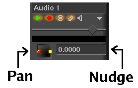
Pan and nudge for an audio track.
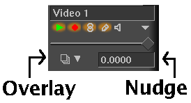
Overlay mode and nudge for a video track.
The nudge is the amount the track is shifted left or right during playback. The track is not displayed shifted on the timeline, but it is shifted when it’s played back. This is useful for synchronizing audio with video, creating fake stereo, or compensating for an effect which shifts time, all without tampering with any edits.
Merely enter in the amount of time to shift by to instantly shift the track. Negative numbers make the track play later. Positive numbers make the track play sooner. The nudge units are either seconds or the native units for the track. Select the units by right clicking on the nudge textbox and using the context sensitive menu.
Nudge settings are ganged with the Gang faders toggle and the Arm track toggle.
Use the mouse wheel over the nudge textbox to increment and decriment it.
Next: AUTOMATIC TRACK PANNING, Previous: NUDGING TRACKS, Up: EDITING [Contents]
Audio tracks have a panning box in their patchbay. It may have to be expanded to see it. The panning box is shown here.
Pan and nudge for an audio track.
Position the pointer in the panning box and click/drag to reposition the audio output among the speaker arrangement. The loudness of each speaker is printed during the dragging operation. The panning box uses a special algorithm to try to allow audio to be focused through one speaker or branched between the nearest speakers when more than 2 speakers are used.
Next: STANDARD AUDIO MAPPINGS, Previous: PANNING TRACKS, Up: EDITING [Contents]
Several convenience functions are provided for automatically setting the panning to several common standards. They are listed in the Audio menu. These functions only affect audio tracks with recording enabled.
Audio->Map LR - This maps every track to its own channel and wraps around when all the channels are allocated. The most common use is mapping track 1 to left & track 2 to right. For more channels, it maps every track to its own speaker.
Audio->Map CLRLRC - This maps 6 tracks to 2 channels. The project should have 2 channels when using this function. Go to Settings->format to set the output channels to 2. This is most useful for downmixing 5.1 audio to stereo.
Audio->Map LRCCLR - This is alternative mapping of 6 tracks to 2 channels.
Next: MANIPULATING TRACKS, Previous: AUTOMATIC TRACK PANNING, Up: EDITING [Contents]
Although Cinelerra lets you map any audio track to any speaker, there are standard mappings you should use to ensure the media can be played back elsewhere. Also, most audio encoders require the audio tracks to be mapped to standard speaker numbers or they won’t work.
In the channel position widget See SETTING PROJECT ATTRIBUTES, the channels are numbered to correspond to the output tracks they are rendered to. For stereo, the source of channel 1 needs to be the left track and the source of channel 2 needs to be the right track.
For 5.1 surround sound, the sources of the 6 channels need to be in the order of center, front left, front right, back left, back right, low frequency effects. If the right tracks aren’t mapped to the right speakers, most audio encoders won’t encode the right information if they encode anything at all. The low frequency effects track specifically can’t store high frequencies in most cases.
Next: TWO SCREEN EDITING, Previous: STANDARD AUDIO MAPPINGS, Up: EDITING [Contents]
Tracks in Cinelerra either contain audio or video. There is no special designation for tracks other than the type of media they contain. When you create a new project, it contains a certain number of default tracks. You can still add or delete tracks from a number of menus. The Tracks menu contains a number of options for dealing with multiple tracks simultaneously. Each track itself has a popup menu which affects one track.
Bring up the popup menu by moving over a track and right clicking. The popup menu affects the track whether it’s armed or not.
Move up and move down moves the one track up or down in the stack. The move operations wrap around so move the top track up to put it on the bottom. Move the bottom track down to put it on top.
Delete track deletes the track.
Operations in the Tracks menu affect only tracks which are armed.
Tracks->Move tracks up and Tracks->Move tracks down shift all the armed tracks up or down the stack. Tracks of the same type wrap around but tracks of different types don’t.
Delete tracks deletes the armed tracks.
Delete last track deletes the last track, whether it’s armed or not. Holding down the d key quickly deletes all the tracks.
Concatenate tracks is more complicated. It takes every playable track and concatenates it to the end of the first armed tracks. If there are two armed tracks followed by two playable tracks, the concatenate operation puts the two playable tracks after the two armed tracks. If there are three playable tracks instead, two tracks are put after the armed tracks and a third track is put on the end of the first armed track. The destination track wraps around until all the playable tracks are concatenated.
Finally, you’ll want to create new tracks. The Audio and Video menus each contain an option to add a track of their specific type. In the case of audio, the new track is put on the bottom of the timeline and the output channel of the audio track is incremented by one. In the case of video, the new track is put on the top of the timeline. This way, video has a natural compositing order. New video tracks are overlayed on top of old tracks.
Next: DRAG AND DROP EDITING, Previous: MANIPULATING TRACKS, Up: EDITING [Contents]
The fastest way to construct a program out of movie files is to load source files in 1 copy of Cinelerra and copy bits of them to another copy of Cinelerra by highlighting sections of the timeline & using the clipboard functions. This allows the full functionality to be applied to the source footage instead of a subset.
Cinelerra also currently supports the conventional way of editing which involves viewing a movie file in one window and viewing the program in another window. Sections of the movie file are defined in one window and transferred to the end of the program in the other window.
The way to begin a two screen editing session is to load some resources. In file->load load some movies with the insertion mode create new resources. You want the timeline to stay unchanged while new resources are brought in. Go to the Resource Window and select the media folder. The newly loaded resources should appear. Drag a resource from the media side of the window over the Viewer window.
There should be enough armed tracks on the timeline to put the sections of source material that you want. If there aren’t, create new tracks or arm more tracks.
In the viewer window seek to the starting point of a clip you want to
use. Use either the slider or the transport controls.
Use the preview region to narrow down the search. Set the
starting point with the in point button.
Seek to the ending point of the clip you want to use. Set the ending
point with the out point button. The
two points should now appear on the timebar and define a clip.
There are several things you can do with the clip now.
 inserts the clip in the timeline, pushing
everything back. If an in point or out point exists on
the timeline it’s inserted there, otherwise it’s inserted after the
insertion point. After that, the insertion point moves to the end of
the clip. If there is no in/out point, the insertion point will be
used as the next splice location. This way you can continuously build
up the program by splicing.
inserts the clip in the timeline, pushing
everything back. If an in point or out point exists on
the timeline it’s inserted there, otherwise it’s inserted after the
insertion point. After that, the insertion point moves to the end of
the clip. If there is no in/out point, the insertion point will be
used as the next splice location. This way you can continuously build
up the program by splicing.
 overwrites the region of the
timeline with the clip. If an in point or out point
exists on the timeline it’s overwritten there, otherwise it’s
overwritten after the insertion point. If a region is highlighted or
both in and out points exist the difference between the active region
and the clip length is deleted.
overwrites the region of the
timeline with the clip. If an in point or out point
exists on the timeline it’s overwritten there, otherwise it’s
overwritten after the insertion point. If a region is highlighted or
both in and out points exist the difference between the active region
and the clip length is deleted.
 generates a new clip for the
resource window containing the affected region but doesn’t change the
timeline. Every clip has a title and a description. These are
optional.
generates a new clip for the
resource window containing the affected region but doesn’t change the
timeline. Every clip has a title and a description. These are
optional.
Two screen editing can be done purely by keybard shortcuts. When you move the pointer over any button a tooltip should appear, showing what key is bound to that button. In the Viewer window, the number pad keys control the transport and the [ ] v keys perform in/out points and splicing.
Next: DRAGGING EDITS, Previous: TWO SCREEN EDITING, Up: EDITING [Contents]
The answer is yes, you can you create a bunch of clips and drag them on the timeline. You can also drag edits around the timeline.
Load some files using file->load. Set the insertion mode to Create new resources. This loads the files into the Resource Window. Create some audio and video tracks on the timeline using the video and audio menus.
Open the Media folder in the resource window. Drag a media file from the resource window to the timeline. If the media has video, drag it onto a video track. If the media is pure audio, drag it onto an audio track.
Cinelerra fills out the audio and video tracks below the dragging cursor with data from the file. This affects what tracks you should create initially and which track to drag the media onto. If the media has one video track and two audio tracks, you’ll need one video track and two audio tracks on the timeline and the media should be dragged over the first video track. If the media has audio only you’ll need one audio track on the timeline for every audio track in the media and the media should be dragged over the first audio track.
When dragging, the media snaps to the start of track if the track is empty. If there are edits on the track, the media snaps to the nearest edit boundary.
You can also drag multiple files from the resource window. Either draw a box around the files, use SHIFT, or use CTRL when selecting files. When you drop the files in the timeline, they are concatenated.
SHIFT-clicking on media files extends the number of highlighted selections. CTRL-clicking on media files selects additional files one at a time.
Next: SPLITTING & JOINING EDITS, Previous: DRAG AND DROP EDITING, Up: EDITING [Contents]
In the timeline there is further dragging functionality. To enable the
dragging functionality of the timeline, select the arrow toggle
![]() . Move over an edit and drag it. If more than one track
is armed, Cinelerra will drag all the edits which start on the same
position as the edit the cursur is currently over. During this type of
dragging operation the destination snaps to the nearest boundary. The
edit is always inserted at the boundary while shifting the later edits
right.
. Move over an edit and drag it. If more than one track
is armed, Cinelerra will drag all the edits which start on the same
position as the edit the cursur is currently over. During this type of
dragging operation the destination snaps to the nearest boundary. The
edit is always inserted at the boundary while shifting the later edits
right.
Dragging edits to different boundaries allows you to sort music playlists, sort movie scenes, and give better NAB demos but not much else.
The default dragging mode is constrained to edit boundaries.
Hold CTRL while dragging to enter free dragging mode. Free dragging works when moving existing edits in the timeline or when dragging an asset from the resource window to the timeline. It’s not currently implemented for dragging effects.
Free dragging can be entered in I beam  or arrow
![]() mode by holding CTRL 1st, then pressing the button.
mode by holding CTRL 1st, then pressing the button.
In this mode, the destination of the edit is any arbitrary position instead of a boundary between 2 edits. Free dragging is most useful for moving a lone edit on a silent track or repositioning a single edit without affecting any edits after it.
An asset in the resource window can be free dragged into the timeline by 1st left click dragging, then pressing CTRL to enter free dragging mode. Pressing CTRL in the resource window before dragging causes it to select multiple items.
The behavior of free dragging is different when dragging with the left button or the right button.
Free dragging with the left button causes an insert at the destination & shifts the neighbors at the source position left to replace the source edit. Free dragging with the right button overwrites the existing edits at the destination & leaves a gap where the source position was.
Only left button insert dragging is supported when the source is in the resource window or in constrained dragging. The right button in these modes activates a context menu.
When free dragging to the same track, the behavior of left button insert mode is different because no material is added to the destination track or taken out of the source track. The only behavior is a shift of the source edit left or right. When shifting left, the neighboring material on the left is moved to the right. When shifting right, the neighboring material on the right is moved to the left.
Right button overwrite mode in a single track behaves the same as going to a different track.
Next: CUT AND PASTE EDITING, Previous: DRAGGING EDITS, Up: EDITING [Contents]
Because dragging in the timeline only moves whole edits, an extra step
is required to move part of an edit. Use the razor button
 to split an edit at the cursor position. It requires a
single point to be selected rather than a region.
to split an edit at the cursor position. It requires a
single point to be selected rather than a region.
To join 2 edits created by a razor operation, press delete or edit->clear when the cursor is on top of the boundary. The edit ending & start must be contiguous for them to join.
Next: TRIMMING, Previous: SPLITTING & JOINING EDITS, Up: EDITING [Contents]
This is the traditional method of editing in audio editors. In the case of Cinelerra, you either need to start a second copy of Cinelerra and copy from one copy to the other, copy from different tracks in the same copy, or load a media file into the Viewer and copy from there.
Load some files onto the timeline. To perform cut and paste editing
select the i-beam toggle. Select a region of the
timeline and select the  cut button to cut it. Move the
insertion point to another point in the timeline and select the
cut button to cut it. Move the
insertion point to another point in the timeline and select the
 paste button. Assuming no in/out points are defined on
the timeline this performs a cut and paste operation.
paste button. Assuming no in/out points are defined on
the timeline this performs a cut and paste operation.
If in/out points are defined, the insertion point and highlighted region are overridden by the in/out points for clipboard operations. Thus, with in/out points you can perform cut and paste in drag and drop mode as well as cut and paste mode.
When editing audio, it is customary to cut from one part of a waveform into the same part of another waveform. The start and stop points of the cut are identical in each waveform and might be offset slightly, while the wave data is different. It would be very hard to highlight one waveform to cut it and highlight the second waveform to paste it without changing the relative start and stop positions.
One option for simplifying this is to open a second copy of Cinelerra, cutting and pasting to transport media between the two copies. This way two highlighted regions can exist simultaneously.
Another option is to set in/out points for the source region of the source waveform and set labels for the destination region of the destination waveform. Perform a cut, clear the in/out points, select the region between the labels, and perform a paste.
A final operation in cut and paste editing is the edit->clear operation. If a region is highlighted or in/out points exist, the affected region is cleared by edit->clear. But if the insertion point is over an edit boundary and the edits on each side of the edit boundary are the same resource, the edits are combined into one edit comprised by the resource. The start of this one edit is the start of the first edit and the end of this one edit is the end of the second edit. This either results in the edit expanding or shrinking.
A key concept in Cinelerra is pasting silence. To move media right without pasting something on the left, you have to select a region on the left side of the edit, then go to edit->paste silence. Then the media is shifted right with silence in front of it. To adjust the position of the media, the silence region is then trimmed or cut to adjust its length. The silence region has edit boundaries just like a normal edit for trimming.
Next: THE EDIT INFO DIALOG, Previous: CUT AND PASTE EDITING, Up: EDITING [Contents]
With some edits on the timeline it’s possible to do trimming. By trimming you shrink or grow the edit boundaries by dragging them. In either drag and drop mode or cut and paste mode, move the cursor over an edit boundary until it changes shape. The cursor will either be an expand left or an expand right. If the cursor is an expand left, the dragging operation affects the beginning of the edit. If the cursor is an expand right, the dragging operation affects the end of the edit.
When you click on an edit boundary to start dragging, the mouse button number determines which dragging behavior is going to be followed.
The effect of each drag operation not only depends on the behavior button but whether the beginning or end of the edit is being dragged. When you release the mouse button, the trimming operation is performed.
In a Drag all following edits operation, the beginning of the edit either cuts data from the edit if you move it forward or pastes new data from before the edit if you move it backward. The end of the edit pastes data into the edit if you move it forward or cuts data from the end of the edit if you move it backward. All the edits thereafter shift. Finally, if you drag the end of the edit past the start of the edit, the edit is deleted.
In a Drag only one edit operation, the behavior is the same when you drag the beginning or end of an edit. The only difference is none of the other edits in the track shift. Instead, anything adjacent to the current edit expands or shrinks to fill gaps left by the drag operation.
In a Drag source only operation, nothing is cut or pasted. If you move the beginning or end of the edit forward, the source reference in the edit shifts forward. If you move the beginning or end of the edit backward, the source reference shifts backward. Where the edit appears in the timeline remains the same but the source shifts.
For all file formats besides still images, the extent of the trimming operation is clamped to the source file length. Attempting to drag the start of the edit beyond the start of the source clamps it to the source start.
In all trimming operations, all edits which start on the same position as the cursor when the drag operation begins are affected. Unarm tracks to prevent edits from getting affected.
Next: EDIT MENU TOOLS, Previous: TRIMMING, Up: EDITING [Contents]
Right click on an edit -> edit info... to get the edit info dialog for the edit. This provides the raw fields in the edit in text form.
The biggest use of this has been fixing synchronization problems. Edit positions can be copied here. Changes here can be undone but redo may not work if the changes corrupted the EDL.
The values are in units of the project sample rate or frame rate.
This method doesn’t protect against corrupting the EDL. The main use is copying the values to another edit in another edit info dialog so the 2 edits are synchronized.
Previous: THE EDIT INFO DIALOG, Up: EDITING [Contents]
This is commonly used for making slide shows. When still photos are loaded from the load dialog in new concatenate mode, they’re inserted in the timeline with a duration of 1 frame & the project frame rate is set to 1fps. You can load a bunch of photos in this mode, then customize the project frame rate & use the edit length command to set the length of all of them.
Alternatively, when photos are pasted from the resource window using the asset context menu, 1 frame is pasted. This too can be customized with the edit length command.
To set the length of an edit or multiple edits in the timeline, select the region which contains the edits to be modified. Now select Edit -> Edit Length... to activate the edit length popup. The duration of the edits can be set by entering the desired edit length in seconds. Pressing OK will change all of the selected edits (in armed tracks) to the specified length.
Cinelerra doesn’t have a concept of locked audio & video tracks or a track type consisting of combined audio & video. It makes some things harder but is generally simpler. Since the audio & video are on independent tracks, loading media in concatenate mode will result in the audio & video getting slightly offset after each file.
Other problems are in the process of editing, it’s important to have Settings->align cursor on frames to make the audio follow the video, but even this is prone to small glitches after many edits.
Align edits tries to fix synchronization after a load or many edits.
To use this feature, select a region which contains all of the edits to be aligned in the timeline. Only edits that are 100% inside the selected area will be used. Arm the tracks to be affected by the alignment. The first armed track is the master track to which all the other tracks are synchronized. For best results, the master track is usually a video track & the slave tracks are usually audio tracks. Video has the less quantized values of time, so is less prone to glitches.
Now go to Edit -> Align Edits to bring up the alignment options. The simplest alignment operation has all these options disabled. That preserves all the edits in the slave tracks, inserting silence or truncating them so they line up with the same numbered edits in the master track. The source start in the edits is unaffected by the alignment process.
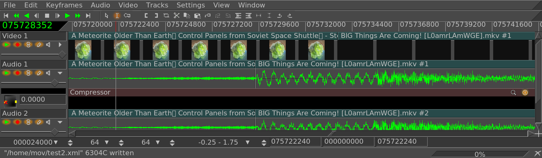
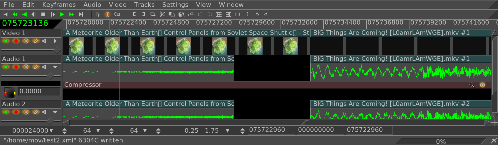
In typical usage, the best results will be with all the options enabled. They should only be disabled if the result is complete garbage.
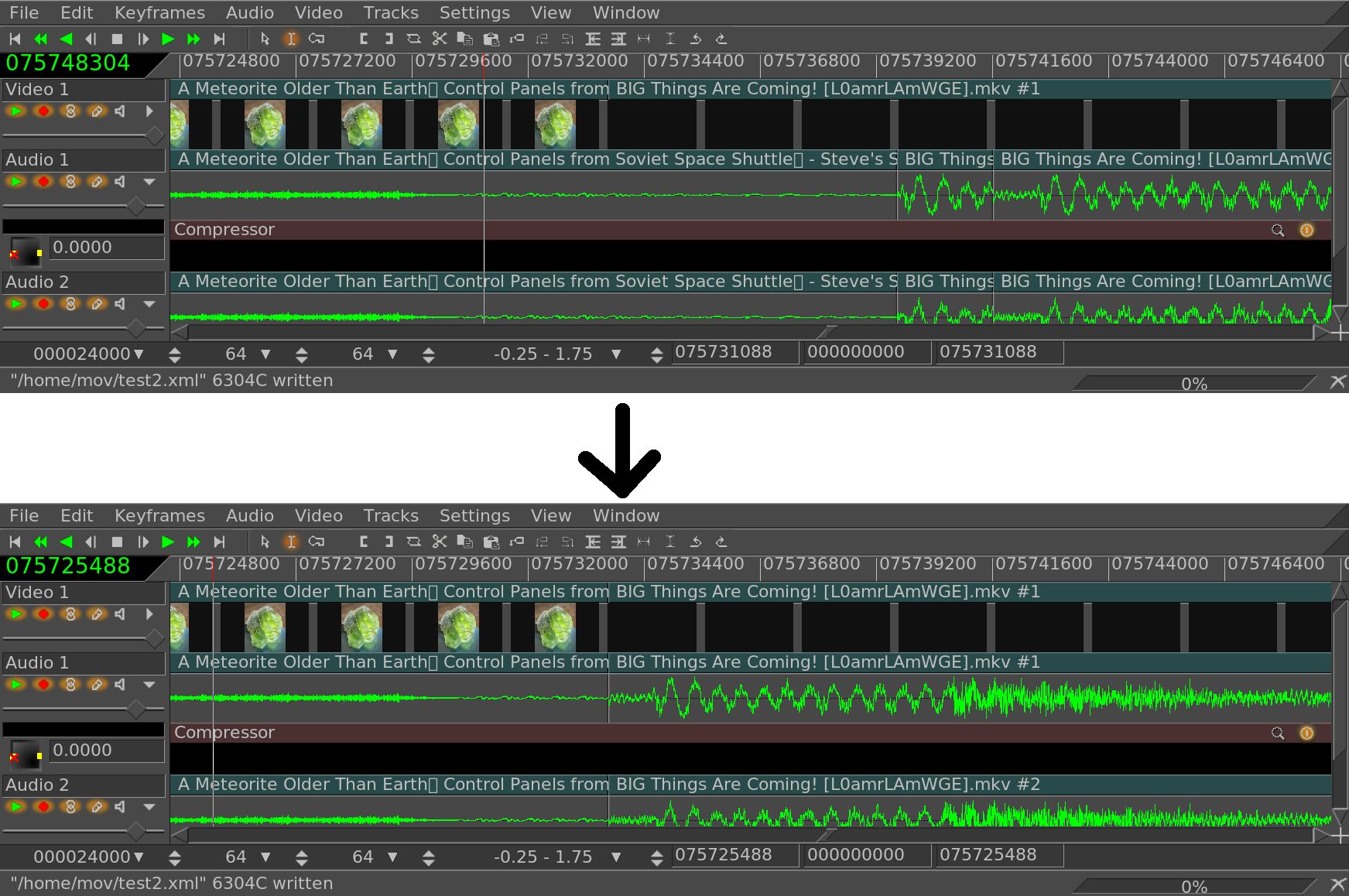
This option is most useful when the master & slave tracks come from the same assets. To combine audio & video from different assets & keep them synchronized with align edits, the best option is to import the combined audio & video as a nested EDL.
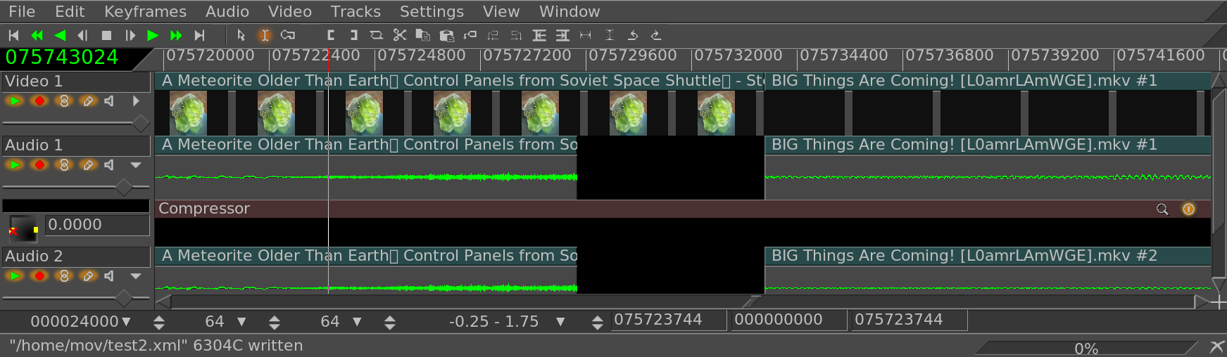
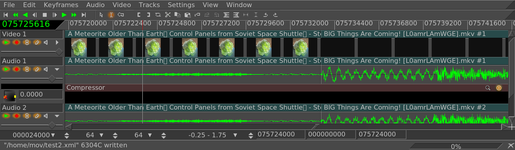
If silence already exists at the end of a slave edit, the extend edits option currently won’t extend the slave edit but will extend the silence. There’s a ballooning amount of complexity in what is mainly a toy.
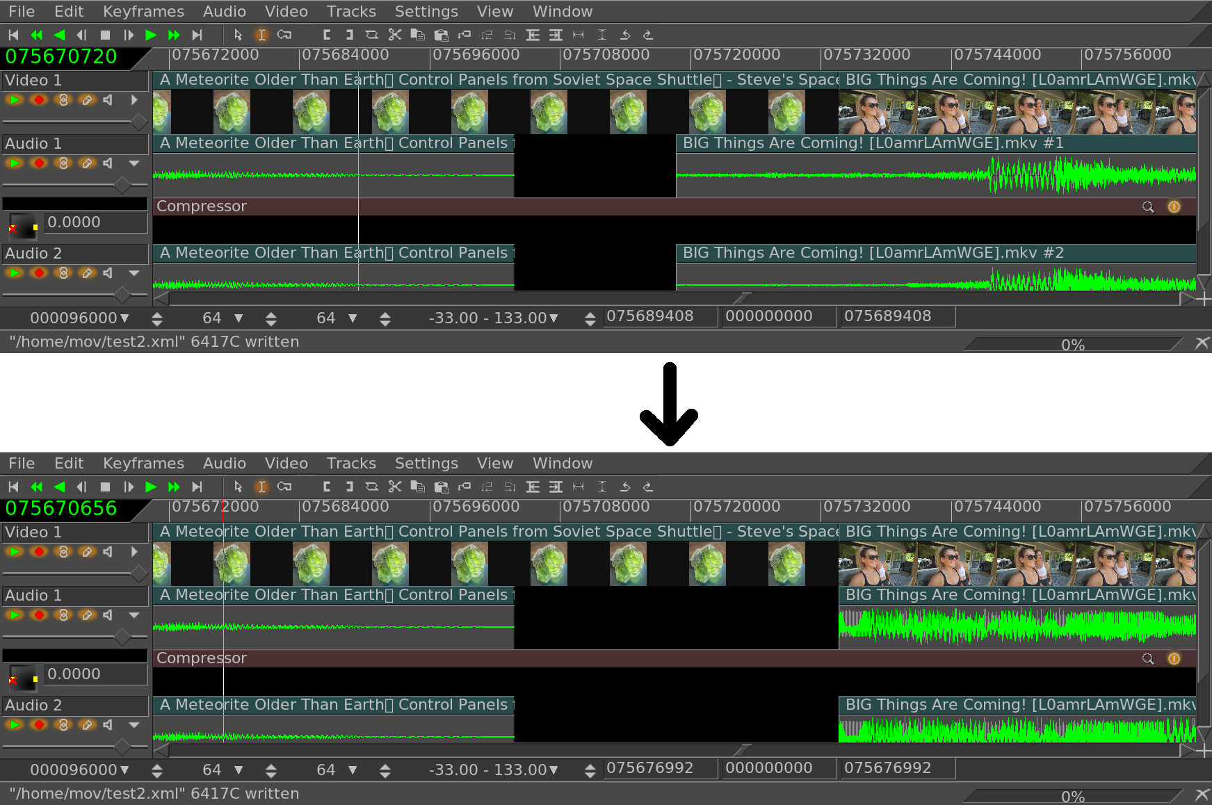
Alignment with labels
Alignment currently does not affect label positions. They stay with the master track.
Alignment with keyframes & effects
Depending on Settings->edit effects & Settings->Keyframes follow edits, the alignment process tries to keep the effects & keyframes synchronized with the changes to the edits. Truly preserving the effects would require a 2nd full alignment function just for effects. For the best results, effects should span the entire track if alignment is going to be needed.
This reverses the order of the selected edits & is commonly used for music playlists, slide shows. Highlight completely the edit areas you would like reversed and then go to Edit -> Reverse Edits.
This randomizes the order of the selected edits & is commonly used for music playlists, slide shows. Highlight completely the edit areas you would like reversed and then go to Edit -> Shuffle Edits.
Next: SETTING PROJECT ATTRIBUTES, Previous: EDITING, Up: TOP [Contents]
This section is for general usage of the effects. For notes on each effect, go to See EFFECTS NOTES.
It would be sufficient to perform all changes to the timeline using editing operations, but this isn’t very extensible. Certain timeline changes should produce a different effect in the output without involving a unique procedure to apply each change. This is why we have effects.
Effects fall into three categories, and each effect in a category is applied using the same procedure.
| • REALTIME EFFECTS: | ||
| • RENDERED EFFECTS: | ||
| • TRANSITIONS: | ||
| • LADSPA EFFECTS: | ||
| • EFFECT KEYFRAMES: | ||
| • EFFECT PRESETS: |
Next: RENDERED EFFECTS, Up: GENERAL EFFECT USAGE [Contents]
These are layered under the track they apply to. They process the track when the track is played back, with no permanent storage of the output except when the project is rendered.
APPLYING REALTIME EFFECTS
All the realtime effects are listed in the resource window, divided into two groups: audio effects and video effects. Audio effects should be dragged from the resource window onto audio tracks. Video effects should be dragged onto video tracks.
If there is data on the destination track, the effect is applied to the entire track. If there is no data on the track the effect is deleted. Finally, if a region of the track is selected the effect is pasted into the region, regardless of whether there is data.
Some of the effects don’t process data but synthesize data. In the case of a synthesis effect, you’ll want to select a region of the track so the dragging operation pastes it without deleting it.
When dragging more than one effect onto a track, you’ll see the effects layering from top to bottom, on the bottom of the track. When the track is played back, effects are processed from top to bottom. The output of the top effect becomes the input of the bottom effect and so on and so forth.
In addition to dragging from the resource window, there are 2 other methods of applying them:
Right click on a track and select Attach effect from the popup. The attach effect dialog gives you more control than pure dragging and dropping. For one thing, the attach effect dialog lets you attach two more types of effects: shared effects and shared tracks. Select a plugin from the Plugins column and hit Attach under the plugins column to attach it. The effect is the same as if the effect was dragged from the resource window.
Select Audio->Attach effect... or Video->Attach effect to attach a realtime effect to all the recordable tracks simultaneously. The advantage with this is most of the time you want to attach the same effect to all the audio tracks and the other two methods require repeating the same work for every track.
The menu interface has an option called Attach single standalone and share others. Enable this to make the first track get a standalone effect and to have the other tracks share the standalone effect. Most of the time, you want this to be on.
When an effect exists under a track, it most often needs to be configured. Go to the effect and right click on it to bring up the effect popup. In the effect popup is a show option. The show option causes the GUI for the effect to appear under the cursor. Most effects have GUI’s but some don’t. If the effect doesn’t have a GUI, nothing pops up when the show option is selected. When you tweek parameters in the effect GUI, the parameters normally effect the entire duration of the effect.
| • REALTIME EFFECT TYPES: | ||
| • EDITING REALTIME EFFECTS: |
Next: EDITING REALTIME EFFECTS, Up: REALTIME EFFECTS [Contents]
The two other effect types supported by the Attach Effect dialog are recycled effects. In order to use a recycled effect, three requiremeents must be met:
In the case of a shared effect, these conditions must be true. In the case of a shared track, there merely must be another track on the timeline of the same type as the track you’re applying an effect to. If you right clicked on a video track to attach an effect, there won’t be anything in the shared tracks column if no other video track exists. If you right clicked on an audio track there won’t be anything in the shared track column if no other audio track exists.
If shared effects or shared tracks are available, they appear in the shared effects and shared tracks columns. The attach button under each column causes anything highlighted in the column to be attached under the current track.
Shared effects and shared tracks allow very unique things to be done. In the case of a shared effect, the shared effect is treated like a copy of the original effect except in the shared effect the GUI can’t be brought up. All configuration of the shared effect is determined by the GUI of the original effect and only the GUI of the original effect can be brought up.
When a shared effect is played back, it’s processed just like a normal effect except the configuration is copied from the original effect. Some effects detect when they are being shared, like the reverb effects and the compressor. These effects determine what tracks are sharing them and either mix the two tracks together or use one track to stage some value. The reverb mixes tracks together to simulate ambience. The compressor uses one of the sharing tracks as the trigger.
When an original track has a shared track as one of its effects, the shared track itself is used as a realtime effect. This is more commonly known as bouncing tracks but Cinelerra achieves the same operation by attaching shared tracks. The fade and any effects in the shared track are applied to the original track. Once the shared track has processed the data, the original track performs any effects which come below the shared track and then composites it on the output.
In addition, once the shared track has processed the output of the
original track like a realtime effect, the shared track mixes itself
into the output with it’s settings for pan, mode, and projector. Thus,
two tracks are mixing the same data on the output. Most of the time
you don’t want the shared track to mix the same data as the original
track on the output. You want it to stop right before the mixing stage
and give the data back to the original track. Do this by enabling the
 mute toggle next to each track for whom you don’t
want to mix on the output.
mute toggle next to each track for whom you don’t
want to mix on the output.
Suppose you were making video and you did want the shared track to composite the original track’s data on the output a second time. In the case of video, the video from the shared track would always appear under the video from the original track, regardless of whether it was on top of the original track. This is because shared tracks are composited in order of their attachment. Since it’s part of the original track it has to be composited before the original track is composited.
Previous: REALTIME EFFECT TYPES, Up: REALTIME EFFECTS [Contents]
Many operations exist for manipulating effects once they are in the timeline. Because mixing effects and media is such complex business, the methods used in editing effects aren’t as concise as cutting and pasting. Some of the editing happens by dragging in/out points, some of the editing happens through popup menus, and some of it happens by dragging effects.
Normally when you edit tracks, the effects follow the editing decisions. If you cut from a track, the effect shrinks. If you drag edit in/out points, the effect changes length. This behavior can be disabled by selecting Settings->edit effects in the project window. This decouples effects from editing operations, but what if you just want to edit the effects?
Move the timeline cursor over the effect borders until it changes to a resize left or resize right icon. In this state, if you drag the end of the effect, it performs an edit just like dragging the end of a track does.
The three editing behaviors of track trimming apply to effect trimming and they are bound to the mouse buttons that you set in interface preferences. See INTERFACE. When you perform a trim edit on an effect, the effect boundary is moved by dragging on it. Unlike track editing, the effect has no source length. You can extend the end of an effect as much as desired without being limited.
Also unlike track editing, the starting position of the drag operation doesn’t bind the edit decision to media. The media the effect is bound to doesn’t follow effect edits. Other effects; however, do follow editing decisions made on an effect. If you drag the end of an effect which is lined up to effects on other tracks, the effects on the other tracks will be edited while the media stays the same.
What happens if you trim the end of an effect in, leaving a lot of unaffected time near the end of the track? When you drag an effect in from the Resource Window you can insert the effect in the portion of the row unoccupied by the trimming operation. Realtime effects are organized into rows under the track. Each row can have multiple effects.
In some cases you’ll want a trimming operation to change only one row of effects. This can be achieved by first positioning the insertion point on the start or end of the effect. Then press shift while beginning the trimming operation. This causes the operation to change only one row of effects.
In addition to trimming, you can move effects up or down. Every track can have a stack of effects under it. By moving an effect up or down you change the order in which effects are processed in the stack. Go to an effect and right click to bring up the effect menu.
The Move up and Move down options move the effect up or down. The effects wrap around so moving the top one up wraps it around to the bottom. Moving the bottom effect down wraps it around to the top. This allows a new effect to be put on top after being attached.
When you’re moving effects up or down, be aware that if they’re shared as shared effects, any references will be pointing to a different effect after the move operation.
Finally, there’s dragging of effects. Dragging effects works just like
dragging edits. You must select the ![]() arrow to enter drag and
drop mode before dragging effects. The effects snap to media
boundaries, effect boundaries, and tracks. Be aware if you drag a
reference to a shared effect, the reference will usually point to the
wrong effect afterwards.
arrow to enter drag and
drop mode before dragging effects. The effects snap to media
boundaries, effect boundaries, and tracks. Be aware if you drag a
reference to a shared effect, the reference will usually point to the
wrong effect afterwards.
Right click on an effect to bring up a menu for the effect. Select attach... to change the effect or change the reference if it is a shared effect.
Next: TRANSITIONS, Previous: REALTIME EFFECTS, Up: GENERAL EFFECT USAGE [Contents]
Another type of effect is performed on a section of the track and the result stored somewhere before it is played back. The result is usually pasted into the track to replace the original data.
In 15 years, the only effect we actually ever rendered with this feature was normalize. We’ve never rendered an effect which could be applied on the timeline, even though this feature supports rendering realtime effects.
This feature was implemented back when computers were too slow to play back anything in realtime. Decent sounding reverb took a long time & was considered major number crunching.
The rendered effects are not listed in the resource window but instead are accessed through the Audio->Render effect and Video->Render effect menu options. Each of these menu options brings up a dialog for the rendered effect. Rendered effects apply to only one type of track, either audio or video. If no tracks of the type exist, an error pops up.
A region of the timeline to apply the effect to must be defined before selecting Render effect.... If no in/out points and no highlighted region exists, the entire region after the insertion point is treated as the affected region. Otherwise, the region between the in/out points or the highlighted region is the affected region.
Secondly, the tracks to apply the rendered affect to need to be armed. All other tracks are ignored.
Finally, the rendered affect processes certain track attributes when it reads its input data but not others. Transitions in the affected track are applied. Nudge is not and effects are not. This allows the new data to be pasted into the existing position without changing the nudge value.
In the render effect dialog is a list of all the realtime and all the rendered effects. The difference here is that the realtime effects are rendered to disk and not applied under the track. Highlight an effect in the list to designate it as the one being performed.
Define a file to render the effect to in the Select a file to
render to box. The magnifying glass allows file
selection from a list.
Select a file format which can handle the track type. The
wrench allows configuration specific to the file format.
There is also an option for creating a new file at each label. If you have a CD rip on the timeline which you want to divide into different files, the labels would become dividing points between the files if this option were selected. When the timeline is divided by labels, the effect is re-initialized at every label. Normalize operations take the peak in the current file and not in the entire timeline.
Finally there is an insertion strategy just like in the render dialog. It should be noted that even though the effect applies only to audio or video, the insertion strategy applies to all tracks just like a clipboard operation.
When you click OK in the effect dialog, it calls the GUI of the effect. If the effect is also a realtime effect, a second GUI appears to prompt for acceptance or rejection of the current settings. After accepting the settings, the effect is processed.
Next: LADSPA EFFECTS, Previous: RENDERED EFFECTS, Up: GENERAL EFFECT USAGE [Contents]
When one edit ends and another edit begins, the default behaviour is to have the first edit’s output immediately become the output of the second edit when played back. Transitions are a way for the first edit’s output to become the second edit’s output with different variations.
Cinelerra supports audio and video transitions, all of which are listed in the resource window. Transitions may only apply to the matching track type. Transitions under audio transitions can only apply to audio tracks. Transitions under video transitions can only apply to video tracks.
Load a video file and cut a section from the center so the edit point is visible on the timeline. Go the resource window and click on the Video transitions folder. Drag a transition from the transition list onto the second video edit on the timeline. A box highlights over where the transition will appear. Releasing it over the second edit applies the transition between the first and second edit.
You can now scrub over the transition with the transport controls and watch the output in the Compositor window. Scrubbing with the insertion point doesn’t normally show transitions because the transition durations are usually too short. The exact point in time when the transition takes effect isn’t straightforward. It starts when the second edit begins and lasts a certain amount of time into the second edit. Therefore, the first asset needs to have enough data after the edit point to fill the transition into the second edit.
Once the transition is in place, it can be edited similarly to an effect. Move the pointer over the transition and right click to bring up the transition menu. The show option brings up specific parameters for the transition in question if there are any. The length option adjusts the length of the transition in seconds. Once these two parameters are set, they are applied to future transitions until they are changed again. Finally, the detach option removes the transition from the timeline.
Dragging and dropping transitions from the Resource window to the Program window can be really slow and tiring. Fortunately, once you drag a transition from the Resource window, the U and u keys will paste the same transition. The U key pastes the last video transition and the u key pastes the last audio transition on all the recordable tracks. If the insertion point or in point is over an edit, the beginning of the edit is covered by the transition.
It should be noted that when playing transitions from the timeline to a hardware accelerated video device, the hardware acceleration will usually be turned off momentarily during the transition and on after the transition in order to render the transition. Using an unaccelerated video device for the entire timeline normally removes the disturbance.
Next: EFFECT PRESETS, Previous: TRANSITIONS, Up: GENERAL EFFECT USAGE [Contents]
LADSPA effects are supported in realtime and rendered mode for audio but have not been tested in a long time because they just weren’t very good.
The LADSPA plugins you get from the internet vary in quality. Most can’t be tweeked in realtime very easily and work better when rendered. Some crash and some can only be applied to one track due to a lack of reentrancy. Although Cinelerra implements the LADSPA interface as accurately as possible, multiple tracks of realtime, simultaneous processing go beyond the majority of LADSPA users. LADSPA effects appear in the audio folder as the hammer and screwdriver, to signify that they are Plugins for Linux Audio Developers.
LADSPA Effects are enabled merely by setting the LADSPA_PATH environment variable to the location of your LADSPA plugins or putting them in the /usr/lib/cinelerra directory.
Previous: LADSPA EFFECTS, Up: GENERAL EFFECT USAGE [Contents]
Save and recall all the settings for an effect by using the presets window. Bring up the effect context menu by right clicking on the effect on the timeline. Go to Presets... to bring up the window. Save the current keyframe to a preset by entering a title in Preset title and clicking save. Highlight an existing preset & click save to overwrite it.
Recall the settings in a preset by highlighting it and clicking
Load. Load will create a keyframe if  auto
keyframes are enabled. Delete a preset by highlighting it and clicking
Delete.
auto
keyframes are enabled. Delete a preset by highlighting it and clicking
Delete.
Double clicking a preset also loads it. OK in the preset window causes the highlighted preset to be loaded.
Factory presets have a *. These may not be overwritten.
Next: COMPOSITING, Previous: GENERAL EFFECT USAGE, Up: TOP [Contents]
When you play media files in Cinelerra, the media files have a certain number of tracks, a certain frame size, a certain sample size, and so on and so forth. No matter what the media file has; however, it is still played back according to the project attributes. If an audio file’s samplerate is different than the project attributes, it is resampled. If a video file’s frame size is different than the project attributes, it is composited on a black frame, either cropped or bordered with black.
The project attributes are adjusted in Settings->Set Format and in to a more limited extent in File->New. When you adjust project settings in file->new a new timeline is created with no data. Every timeline created from this point uses the same settings. When you adjust settings in settings->format, the timeline is not recreated with no data but every timeline created from this point uses the same settings.
In addition to the traditional settings for sample rate, frame rate, frame size, Cinelerra uses some unusual settings like channel positions, color model, and aspect ratio.
| • AUDIO CHANNEL POSITIONS: | ||
| • COLOR MODEL: | ||
| • ASPECT RATIO: |
Next: COLOR MODEL, Up: SETTING PROJECT ATTRIBUTES [Contents]
The currently enabled audio channels and their positions in the user interface boxes are displayed in the channel position widget.
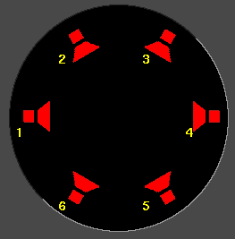
The channels are numbered. When rendered, the output from channel 1 is rendered to the first output track in the file or the first soundcard channel of the soundcard. Later channels are rendered to their successively numbered output tracks.
The audio channel locations correspond to where in the panning widgets each of the audio outputs is. The closer the panning position is to one of the audio outputs, the more signal that speaker gets. Click on a speaker icon and drag to change the audio channel location.
The speakers can be in any orientation. A different speaker arrangement is stored for every number of audio channels since normally you don’t want the same speaker arrangement for different numbers of channels.
Channel positions is the only setting which doesn’t affect the output necessarily. Click on a speaker icon and drag to change the position of a channel. It is merely a convenience so when more than 2 channels are used, the pan controls on the timeline can distinguish between them. It has nothing to do with the actual arrangement of speakers.
But different channels can be positioned very close together to make them have the same output.
Next: ASPECT RATIO, Previous: AUDIO CHANNEL POSITIONS, Up: SETTING PROJECT ATTRIBUTES [Contents]
Color model is very important for video playback because video has the disadvantage of being very slow. Although it isn’t noticeable, audio intermediates contain much more information than the audio on disk and the audio which is played. Audio always uses the highest bandwidth intermediate because it’s fast.
Video intermediates must use the least amount of data for the required quality because it’s slow, but video intermediates still use a higher bandwidth color model than video which is stored and video which is played. This allows more processing to be done with less destruction of the original data.
The video is stored on disk in one colormodel, normally compressed using a YUV derivative. When played back, Cinelerra decompresses it from the file format directly into the format of the output device. If effects are processed, the decompression is into an intermediate colormodel first and the intermediate colormodel is then converted to the format of the output device. The selection of intermediate colormodel determines how accurate and fast the effects are.
Cinelerra colormodels are described using a certain packing order of components and a certain number of bits for each component. The packing order is printed on the left and the bit allocation is printed on the right.
This allocates 8 bits for the R, G, and B channels and no alpha. This is normally used for uncompressed media with low dynamic range.
This allocates an alpha channel to the 8 bit RGB colormodel. It’s used for overlaying multiple tracks.
This allocates 8 bits for Y, U, and V. This is used for low dynamic range operations in which the media is compressed in the YUV color space. Most compressed media is in YUV and this allows it to be processed fast with the least color degradation.
This allocates an alpha channel to the 8 bit YUV colormodel for transparency.
This allocates a 32 bit float for the R, G, and B channels and no alpha. This is used for high dynamic range processing with no transparency.
In order to do effects which involve alpha channels, a colormodel with an alpha channel must be selected. These are RGBA8888, YUVA8888, and RGBA Float. The 4 channel colormodels are notoriously slower than 3 channel colormodels, with the slowest being RGBA Float. Some effects, like fade, work around the need for alpha channels while other effects, like chromakey, require an alpha channel to do anything, so it’s a good idea to try the effect without alpha channels to see if it works before settling on an alpha channel and slowing it down.
The YUV colormodels are usually faster than RGB colormodels when using compressed footage. They also destroy fewer colors than RGB colormodels. If footage stored as JPEG or MPEG is processed many times in RGB, the colors will fade while they won’t if processed in YUV.
Years of working with high dynamic range footage have shown floating point RGB to be the best format for high dynamic range. While 16 bit integers were used in the past, these were too lossy and slow for the amount of improvement.
RGB float doesn’t destroy information when used with YUV source footage. It also supports brightness above 100%. Be aware that some effects, like Histogram, still clip above 100% when in floating point.
Previous: COLOR MODEL, Up: SETTING PROJECT ATTRIBUTES [Contents]
Aspect ratio determines the shape of the video output when using the X11 video output. The numbers in each direction can be any floating point number. When drawn on the screen, video pixels are stretched to match the aspect ratio.
Some file formats, like MPEG video, write the project aspect ratio to the file.
Next: KEYFRAMES, Previous: SETTING PROJECT ATTRIBUTES, Up: TOP [Contents]
A large amount of Cinelerra’s binary size is directed towards compositing. When you remove the letterboxing from a widescreen show, you’re compositing. Changing the resolution of a show, making a split screen, and fading in and out among other things are all compositing operations in Cinelerra. Cinelerra detects when it’s in a compositing operation and plays back through the compositing engine only then. Otherwise, it uses the fastest decoder available in the hardware.
Compositing operations are done on the timeline and in the Compositor window. Shortcuts exist in the Resource window for changing some compositing attributes. Once some video files are on the timeline, the compositor window is a good place to try compositing.
| • THE CAMERA AND PROJECTOR: | ||
| • MASKS: | ||
| • CROPPING: | ||
| • OVERLAY MODES: | ||
| • TRACK AND OUTPUT SIZES: |
Next: MASKS, Up: COMPOSITING [Contents]
In the compositor window, the most important functions are the
camera button and the projector
button. These control operation of the camera and projector. Inside
Cinelerra’s compositing pipeline, the camera determines where in the
source video the temporary is copied from. The projector determines
where in the output the temporary is copied to. The temporary is a
frame of video in Cinelerra’s memory where all graphics processing is
done. Each track has a different temporary which is defined by the
track size. By resizing the tracks you can create splitscreens, pans,
and zooms.
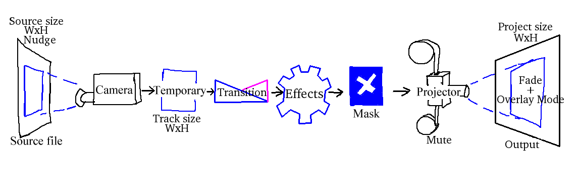
The compositing journey begins by shifting the playback position by the nudge value specified in the patchbay. All operations in the pipeline are shifted by this amount.
Then, if the speed curve has a value other than 1, the read position in the source file is stretched based on the speed curve. The source file is then read into a temporary defined by the track size, using the camera parameters to scale & translate it.
The next step is to apply a transition if one exists. Then the effects are processed from top to bottom. Then, if any masks are defined for the track, they are applied to the track temporary after the effects.
The final step is the projector where fade, overlay mode, projector scaling & translation are applied between the track temporary & the output canvas. If the track is muted, the projector step isn’t performed.
In an audio track, the panning is applied in the last step.
When editing the camera and projector in the compositing window, the first track with record enabled is the track affected. Even if the track is completely transparent, it’s still the affected track. If multiple video tracks exist, the easiest way to select one track for editing is to shift-click on the record icon of the track. This solos the track.
When the projector button is enabled in the compositor window, you’re in projector editing mode. A guide box appears in the video window. Dragging anywhere in the video window causes the guide box to move, hopefully along with the video. shift-dragging anywhere in the video window causes the guide box to shrink and grow along with the video. Once you’ve positioned the video with the projector, you’re ready to master the camera.
Select the camera button to enable camera editing mode.
In this mode, the guide box shows where the camera position is in
relation to past and future camera positions but not where it is in
relation to the source video. Dragging the camera box in the
compositor window doesn’t move the box but instead moves the location
of the video inside the box.
For example, when you drag the camera left, the video moves right. When you drag the camera up, the video moves down. When you shift-drag the camera, the effect is the same as if you zoomed in or out of the source. The intention of the camera is to produce still photo panning, while the intention of the projector is to composite several sources in the same scene.
In the compositing window, there is a popup menu of options for the camera and projector. Right click over the video portion of the compositing window to bring up the menu.
The camera and projector have shortcut operations neither in the popup
menu or represented in video overlays. These are accessed in the
Tool window. Most operations in the Compositor window have a
tool window which is enabled by activating the  question mark.
In the case of the camera and projector, the tool window shows x, y, and z coordinates. By either tumbling or entering text directly, the camera and projector can be precisely positioned. 9 justification types are also defined for easy access. A popular justification operation is upper left projection after image reduction. This is used when reducing the size of video with aspect ratio adjustment.
THE TRANSLATION EFFECT
The translation effect allows simultaneous aspect ratio conversion and reduction but is easier to use if the reduced video is put in the upper left of the temporary instead of in the center. The track size is set to the original size of the video and the camera is centered. The output size is set to the reduced size of the video. Without any effects, this produces just the cropped center portion of the video in the output.
The translation effect is dropped onto the video track. The input dimensions of the translation effect are set to the original size and the output dimensions are set to the reduced size. To put the reduced video in the center section that the projector shows would require offsetting out x and out y by a complicated calculation. Instead, we leave out x and out y at 0 and use the projector’s tool window.
Merely by selecting  left justify and
 top justify, the projector displays the reduced
image from the top left corner of the temporary in the center of the
output.
top justify, the projector displays the reduced
image from the top left corner of the temporary in the center of the
output.
Next: CROPPING, Previous: THE CAMERA AND PROJECTOR, Up: COMPOSITING [Contents]
Masks define a region of the video to either set opaque or transparent.
Another thing the mask tool does is draw paths. Paths are lines while masks are areas. Paths can be simple line drawings or outlines.
Masks can be used in conjunction with another effect to isolate the effect to a certain region of the frame. A copy of one video track may be delayed slightly and unmasked in locations where the one copy has interference but the other copy doesn’t. Color correction may be needed in one section of a frame but not another. A mask can be applied to just a section of the color corrected track while the vanilla track shows through. Removal of boom microphones, airplanes, and housewives are other mask uses.
The order of the compositing pipeline affects what can be done with masks. Mainly, masks are performed on the temporary after effects and before the projector. This means multiple tracks can be bounced to a masked track and projected with the same mask.
Our compositing pipeline graph now has a masking stage. There are 8 possible masks per track. Each mask is defined separately, although they each perform the same operation, whether it’s addition or subtraction, or a path.
To define a mask, go into the Compositor window and enable the
mask toggle.
Now go over the video and click to create a starting point for the mask. Click again in another part of the image to create a new point of the polygon. Every click creates a new point for a mask. The polygon is automatically closed.
To create a point before the last point, select the point before the point to be created. There is no way to insert a point before the 1st point. This is how Google maps has done it & it’s worked well.
Knowing the 1st & last point is essential for animating masks, so the 1st & last points are triangles while the other points are circles. The current point being edited is enlarged.
Once points are defined, they can be moved by ctrl-dragging in the vicinity of the corner. This; however, doesn’t smooth out the curve. The lines are linear by default. To get curves, shift-drag on a point to create control points. Then shift-dragging near a control point causes the control point to move.
Finally, once you have a mask, the mask can be translated in one piece by alt-dragging the mask. Mask editing in Cinelerra is identical to how The Gimp edits masks except in this case the effect of the mask is always on.
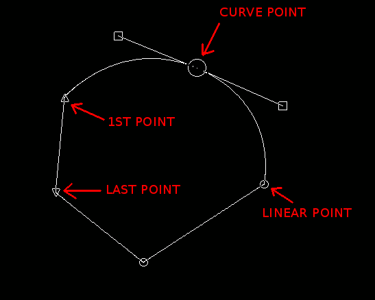
Mask tool window
The masks have many more parameters which couldn’t be represented with video overlays. These are represented in the tool window for masks.
MODE determines if the mask removes data or makes data visible, if it’s a path or a closed polygon. If the mode is subtractive, the mask causes video to disappear. If the mode is additive, the mask causes video to appear and everything outside the mask to disappear.
VALUE determines how extreme the addition or subtraction is. In the subtractive mode, higher values subtract more alpha. In the additive mode, higher values make the region in the mask brighter while the region outside the mask is always hidden.
MASK NUMBER The mask number determines which one of the 8 possible masks we’re editing. Each track has 8 possible masks. When you click-drag in the compositor window, you’re only editing one of the masks. Change the value of mask number to cause another mask to be edited. The previous mask is still active but only the curve overlay for the currently selected mask is visible.
When multiple masks are used, their effects are ORed together. Every mask in a single track uses the same value, mode, feather, radius.
FEATHER The edges of a mask are hard by default but this rarely is desired. The feather parameter determines how many pixels to feather the mask. This creates softer edges but takes longer to render.
RADIUS Only applies to paths & determines the width of the path. Feather is still applied to the edges of the path.
Finally, there are parameters for editing one point on the current mask instead of the whole mask.
EDITING POINT Selects the active point for editing. The points are all numbered from the 1st one created. The active point is drawn enlarged in the compositor window.
X, Y Shows the position of the selected point. Enter text to reposition it.
DELETE POINT Deletes the selected point
MAKE LINEAR This deletes the bezier control points to make the lines linear.
Notes about animating masks are in the keyframe section. See MASK KEYFRAMES
Next: OVERLAY MODES, Previous: MASKS, Up: COMPOSITING [Contents]
Cropping changes the value of the output dimensions and the projector
to reduce the visible picture area. Enable the crop
toggle and the tool window in the compositing
window to perform cropping.
This draws a rectangle over the video. Click-drag anywhere in the video to start a new rectangle. Click-drag over any corner of the rectangle to reposition the corner.
Alt-click in the cropping rectangle to translate the rectangle to any position without resizing it.
The tool window allows text entry of the coordinates and executes the cropping operation. When the rectangle is positioned, hit the do it button in the tool window to execute the cropping operation.
Next: TRACK AND OUTPUT SIZES, Previous: CROPPING, Up: COMPOSITING [Contents]
Every video track has an overlay mode, accessible by expanding the track. The overlay mode is a pulldown menu on the left under the fader. When collapsed, it displays an icon representing the current overlay mode.
Select the expand track toggle to view all
the options for a video track if you can’t see the overlay mode. The
overlay mode of video tracks is normal by default. Select other
modes by clicking the overlay button and selecting an item from the
popup menu.
Overlay modes are processed inside the projector stage of compositing. The different modes are summarized below.
Previous: OVERLAY MODES, Up: COMPOSITING [Contents]
The size of the temporary and the size of the output in our compositing pipeline are independent and variable. This fits into everything covered so far. The camera’s viewport is the temporary size. Effects are processed in the temporary and are affected by the temporary size. Projectors are rendered to the output and are affected by the output size. If the temporary is smaller than the output, the temporary is bordered by blank regions in the output. If the temporary is bigger than the output, the temporary is cropped.
The temporary size is defined as the track size. Each track has a different size. Right click on a track to bring up the track’s menu. Select Resize Track to resize the track to any arbitrary size. Alternatively you can select Match output size to make the track the same size as the output.
The output size is set in either New when creating a new project or Settings->Format. In the Resource window there is another way to change the output size. Right click on a video asset and select Match project size to conform the output to the asset. When new tracks are created, the track size always conforms to the output size specified by these methods.
Next: CAPTURING MEDIA, Previous: COMPOSITING, Up: TOP [Contents]
The fade, mute, mode, pan, mask, speed, camera, projector, transition, or effect data for a track is all stored in keyframes. Keyframes come in many forms: curves, toggles, modes, masks, and so on. How to handle the different types of keyframes is described here.
| • DISPLAYING KEYFRAMES: | ||
| • DEFAULT KEYFRAMES: | ||
| • CURVE KEYFRAMES: | Using rubber band curves | |
| • NAVIGATING CURVE KEYFRAMES: | ||
| • SELECTING BEZIER & LINEAR MODE: | Change curves from linear to curved | |
| • SNAPPING TO NEIGHBOR KEYFRAMES: | ||
| • MUTE KEYFRAMES: | ||
| • AUTOMATIC KEYFRAMES: | ||
| • CAMERA/PROJECTOR KEYFRAMES: | ||
| • MASK KEYFRAMES: | ||
| • EFFECT KEYFRAMES: | ||
| • EDITING KEYFRAMES: | Moving keyframes around | |
| • KEYFRAME SPANNING: | How to change 1 parameter in many keyframes simultaneously |
Next: DEFAULT KEYFRAMES, Up: KEYFRAMES [Contents]
Display keyframes on the timeline for any parameter by using the view menu & selecting the type of keyframe. When keyframes are selected, they are drawn on the timeline over the tracks they apply to.
A faster way to toggle multiple keyframe types is to bring up window->overlays. This window allows toggling of every parameter in the view menu in a persistent window. Click drag in this window to set multiple check boxes at once.
The keyframes->paste operations only affect data types which are currently visible & in recordable tracks. Use the visible status & the track record status to determine what keyframes are edited by the menu operations.
Next: CURVE KEYFRAMES, Previous: DISPLAYING KEYFRAMES, Up: KEYFRAMES [Contents]
Controls are constant for the entire duration of the timeline when no keyframes have been created. The values are stored in a special type of keyframe called the default keyframe when they’re constant. The default keyframe isn’t drawn on the timeline but it can be copied to the clipboard by going to keyframes->copy default keyframe. This menu option copies all the default keyframes for all the data types in every track marked as recordable. Paste the clipboard into a text editor to see the values of all the default keyframes.
The default keyframe can also be overwritten by the clipboard contents. Edit a VALUE in the text editor, copy the complete contents of the text editor & go to keyframes->paste default keyframe to overwrite the timeline value with the value from the text editor.
It should be noted keyframes->paste default keyframe only affects data types which are currently viewable in the View menu, regardless of if their values are in the clipboard.
If view->fade is enabled, hit ALT F, then right click on the rubber band curve to get the keyframe context menu. Edit default keyframe allows editing the default fade keyframe in a window. Another set of copy & paste options in the context menu provide clipboard operations for the default keyframe of just the 1 data type.
Setting constant parameters isn’t very useful sometimes. Change values over time by creating non default keyframes.
Next: NAVIGATING CURVE KEYFRAMES, Previous: DEFAULT KEYFRAMES, Up: KEYFRAMES [Contents]
Fade, Speed, Camera, Projector data is stored in rubber band curves. Go to view->fade to show rubber band curves on the timeline for fade. In either arrow editing mode or i-beam editing mode, move the cursor over the curves in the timeline until it changes into an arrow. Then merely by left clicking and dragging on the curve you can create a keyframe at the position.
After the keyframe is created, click drag on it again to reposition it. When you create a second keyframe on the curve, it creates a smooth ramp.
Right click on a curve keyframe & select Edit keyframe in the context menu to enter text values for it. It can also be changed between bezier & linear in this editor.
Next: SELECTING BEZIER & LINEAR MODE, Previous: CURVE KEYFRAMES, Up: KEYFRAMES [Contents]
There isn’t much room on the timeline for a wide range of curve
values. You need to zoom the curves in and out vertically to have any
variability. This is done by 2 tools: the automation fit button
 and automation zoom menu
  .
.
The automation fit button scales and offsets the vertical range so the selected curves fit in the timeline. The selected curves are defined by the armed tracks, the visible keyframe types, & the highlighted region. If a region of the timeline is highlighted by the cursor, only that region is scaled. If a region is not highlighted, the entire project is scaled. In/out points don’t affect the zoomed region. Alt-f also performs automation fitting.
The automation zoom tumbler manually changes the vertical scaling of the curves by multiples of 2. Alt-Up and Alt-Dn change the automation zoom from the keyboard.
Next: SNAPPING TO NEIGHBOR KEYFRAMES, Previous: NAVIGATING CURVE KEYFRAMES, Up: KEYFRAMES [Contents]
The curve keyframes have linear, locked bezier, & unlocked bezier modes. In linear mode, the keyframe looks like a square and the curves emanating from it are straight. In bezier modes, the keyframe is rounded and has 2 control lines in addition to the rubber band curve lines. In locked bezier mode, the control lines are mirrors & the curve is straight when it passes through the keyframe. In unlocked bezier mode, the control lines have different angles & the curve bends when it passes through the keyframe.
To select the mode for a single keyframe, right click on it to bring up the keyframe menu. Select linear, locked bezier, or unlocked bezier.
To select the mode of multiple keyframes, highlight a region of the timeline, then go to 1 of the Keyframes->change to options. These options change all the keyframes displayed in the View menu, in the highlighted area.
For bezier keyframes, ctrl-dragging on the control lines of a keyframe changes the value of either the input control or the output control. Without ctrl the cursor only affects the central keyframe. This affects the sharpness of the curve. The input and output controls can only be moved vertically.
If the control lines aren’t visible, ctrl-drag on the left or right of the keyframe.
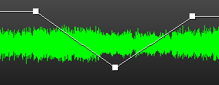
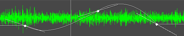
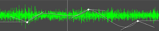
Next: MUTE KEYFRAMES, Previous: SELECTING BEZIER & LINEAR MODE, Up: KEYFRAMES [Contents]
shift-drag on a curve keyframe to make the keyframe snap to the value of either the next or previous keyframe, depending on which exists. This lets you set a constant curve value without having to copy the next or previous keyframe.
Next: AUTOMATIC KEYFRAMES, Previous: SNAPPING TO NEIGHBOR KEYFRAMES, Up: KEYFRAMES [Contents]
Mute is the only toggle keyframe. Mute keyframes determine where the track is processed but not rendered to the output. Click-drag on these curves to create a keyframe. Unlike curves, the mute keyframe has only two values: on or off. Ctrl and shift do nothing on toggle keyframes.
Next: CAMERA/PROJECTOR KEYFRAMES, Previous: MUTE KEYFRAMES, Up: KEYFRAMES [Contents]
You may have noticed when a few fade curves are set up, moving the insertion point around the curves causes the faders to reflect the curve value under the insertion point. This isn’t just to look cool. The faders themselves can create keyframes in automatic keyframe mode. Automatic keyframe mode is usually more useful than dragging curves.
Enable automatic keyframe mode by enabling the automatic keyframe toggle
. In automatic keyframe mode, every time you tweek
a fader it creates a keyframe on the timeline. Since automatic
keyframes affect many parameters, it’s best enabled just before you need
a keyframe and disabled immediately thereafter.
It’s useful to go into the View menu and make the desired parameter visible before performing a change. The location where the automatic keyframe is generated is under the insertion point. If the timeline is playing back during a tweek, several automatic keyframes will be generated as you change the parameter.
When automatic keyframe mode is disabled, adjusting a parameter adjusts the keyframe immediately preceding the insertion point. If two fade keyframes exist and the insertion point is between them, changing the fader changes the first keyframe.
There are many parameters which can only be keyframed in automatic keyframe mode. These are parameters for which curves would take up too much space on the track or which can’t be represented easily by a curve.
Effects, masks, pan, are only keyframable in automatic mode because the number of parameters are different in each individual effect or because they require too many data points to draw on the timeline.
Next: MASK KEYFRAMES, Previous: AUTOMATIC KEYFRAMES, Up: KEYFRAMES [Contents]
Camera and projector automation is represented by X, Y, Z curves. It is
usually cumbersome to adjust camera & projector with the curves so the
compositor window allows direct entry of keyframes by dragging the
image. With a video track loaded, move the insertion point to the
beginning of the track and enable automatic keyframe mode .
Edits in the compositor window only affect the 1st recordable track.
Enable the projector tool in the compositor window. Drag the video output to create keyframes for X & Y translation. Shift drag to zoom & create a keyframe on the Z curve. Clicking the justification buttons in the projector tool similarly create keyframes. Selecting reset projector in the video output’s context menu generates centered keyframes for X Y & Z.
Do ALT F in the timeline window to make the keyframe curves visible on the track.
Move the insertion point to to another time on the timeline. Move the projection again in the compositor window to create more keyframes. Once all the desired keyframes are created, disable automatic keyframe mode.
Now when scrubbing around between times on the timeline, the video projection will interpolate between the keyframes.
If automatic keyframes are off, dragging the video output in the compositor window adjusts the previous keyframe. If the insertion point is between keyframes, it won’t appear to track the drag operation because the position at the insertion point is interpolated between 2 keyframes.
The camera & projector tools perform the same operations on keyframes.
BEZIER CURVES FOR CAMERA/PROJECTOR
By default, the motion paths created by camera & projector are a straight line, but they can be converted to bezier curves via the keyframe menus.
Next: EFFECT KEYFRAMES, Previous: CAMERA/PROJECTOR KEYFRAMES, Up: KEYFRAMES [Contents]
Mask keyframes can only be set by editing a mask in the compositor with
auto keyframes enabled.
The main trick with mask keyframes is the polygons are interpolated between the keyframes by interpolating all the points with the same number. Point 0 is interpolated with point 0. Point 1 is interpolated with point 1. Point 0 is differentiated from the other points to help match the points in the different keyframes.
Feather & radius are interpolated between keyframes but the Mode is whatever the previous keyframe has.
If the number of points changes between keyframes, the results are undefined.
Next: EDITING KEYFRAMES, Previous: MASK KEYFRAMES, Up: KEYFRAMES [Contents]
Effects have a default keyframe which applies to their entire duration &
optionally normal keyframes at points in time. Effect keyframes can be
created by right clicking on the effect, copying the default keyframe &
pasting it as a normal keyframe. They are also created by enabling
auto keyframes & changing a parameter in the effect
GUI. Right click on an effect keyframe to get a context menu for it.
This allows copying single keyframes & pasting them as the default
keyframe or new keyframes. Clipboard operations with multiple keyframes
are done in the Keyframes menu.
To simultaneously change the same parameter in multiple keyframes, See KEYFRAME SPANNING.
Some effect parameters don’t create keyframes, like whether to plot a histogram, the size of the GUI window, "copy to all" in 3 way color. These are saved as defaults.
Whether a parameter isn’t keyframed, changes instantly or is interpolated is done on a case by case basis, but is loosely correlated with the type of parameter. The easiest way to find out what is being interpolated is to create 2 keyframes & scrub between them with the GUI open. The GUI should automatically update to show the current values.
Linear parameters which don’t affect memory usage or time are interpolated. Brightness, histogram points, color curve points, pitch shift amount, translation points, perspective points, scale values are interpolated.
Toggles always copy the current keyframe value.
Time altering parameters are always instant. Resample, reframe, or the reference frame in a motion tracker are instant because they affect time.
Memory altering parameters are always instant. The number of frames in a time average is an example that changes memory usage.
Very slow effects are usually instant. All the parameters in motion effects are instant because they’re slow.
Needs based on experience Some parameters have never needed interpolation, like the position of a reference block in Motion or the number of reflections in Reverb.
Next: KEYFRAME SPANNING, Previous: EFFECT KEYFRAMES, Up: KEYFRAMES [Contents]
THE KEYFRAME MENU
Keyframes can be shifted around and moved between tracks on the timeline using the same cut and paste metaphor as editing media. The keyframe menu performs clipboard operations on multiple keyframes at the same time, as defined by what tracks are armed & what data types are visible. Only the keyframes selected in the view menu are affected by keyframe editing operations.
The most popular keyframe editing operation is replication of some
curve from one track to the other, to make a stereo pair. The first
step is to solo the source track’s record  patch
by shift-clicking on it. Then either set in/out points or
highlight the desired region of keyframes. Go to keyframes->copy
keyframes to copy them to the clipboard. Solo the destination track’s
record patch by shift-clicking on it and
go to keyframes->paste keyframes to paste the clipboard.
patch
by shift-clicking on it. Then either set in/out points or
highlight the desired region of keyframes. Go to keyframes->copy
keyframes to copy them to the clipboard. Solo the destination track’s
record patch by shift-clicking on it and
go to keyframes->paste keyframes to paste the clipboard.
The media editing commands are mapped to the keyframe editing commands by using the shift key instead of just the keyboard shortcut.
Keyframes->copy default keyframe copies the default keyframe to the clipboard, no matter what region of the timeline is selected. The keyframes->paste keyframes function may then be used to paste the clipboard as a non-default keyframe.
If you’ve copied a non-default keyframe, it can be stored as the default keyframe by calling keyframes->paste default keyframe. After using paste default keyframe to convert a non-default keyframe into a default keyframe, you won’t see the value of the default keyframe reflected until all the non-default keyframes are removed.
Finally, there is a convenient way to delete keyframes besides selecting a region and calling keyframes->clear keyframes. Merely click-drag a keyframe before its preceding keyframe or after its following keyframe on the track.
KEYFRAME CONTEXT MENU
Right clicking on a keyframe or a rubber band curve provides a context menu with the same operations as the keyframe menu. The difference is the context menu affects just 1 keyframe at a time. This can be faster than arming tracks & selecting data types to show in the view menu.
The context menu provides an additional Edit keyframe operation to type in the values of a curve keyframe.
EDITING KEYFRAMES IN A TEXT EDITOR
Select copy keyframe or copy default keyframe in the context menu to copy a single keyframe to the clipboard. Paste it in a text editor. Copy it back to the timeline with paste keyframe or paste default keyframe in the context menu.
MOVING KEYFRAMES BETWEEN AUDIO & VIDEO TRACKS
Normally, keyframes from audio tracks can’t be pasted into video tracks & vice versa. Enabling Settings->Interchangeable audio & video keyframes allows keyrfames copied from a track type to be pasted in another track type. The only factor determining the destination is what track is armed. The only real use for this is copying a speed curve to all the tracks.
Previous: EDITING KEYFRAMES, Up: KEYFRAMES [Contents]
To change a single parameter in multiple keyframes without changing the other parameters, highlight a region on the timeline which spans multiple keyframes and adjust the parameter. Instead of a new keyframe being created, the existing keyframes in the span are modified and only the changed parameter is modified.
It doesn’t matter if auto keyframe is enabled. It
only works when the keyframe stores multiple parameters. Only mask and
effect keyframes do this. Other types of keyframes are generated as
usual.
Next: IMPROVING PERFORMANCE, Previous: KEYFRAMES, Up: TOP [Contents]
Ideally, all media would be stored on hard drives, CD-ROM, flash, or DVD and loading it into Cinelerra would be a matter of loading a file. In reality, very few sources of media can be accessed like a filesystem but instead rely on tape transport mechanisms and dumb I/O mechanisms to transfer the data to computers. These media types are imported into Cinelerra through the Record dialog.
The first step in recording is to configure the input device. In Settings->preferences are a number of recording parameters described in configuration See RECORDING. These parameters apply to recording no matter what the project settings are, because the recording parameters are usually the maximum capability of the recording hardware while project settings come and go.
Go to File->record to record a dumb I/O source. This prompts for an output format much like rendering does. Once that’s done, the record window and the record monitor pop up.
The record window has discrete sections. While many parameters change depending on if the file has audio or video, the discrete sections are always the same.
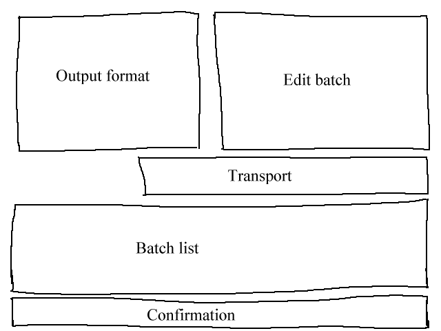
Recording window areas
Recording in Cinelerra is organized around batches. A batch
essentially defines a distinct output file for the recording. For now
you can ignore the batch concept entirely and record merely by hitting
the record button  .
.
The record button opens the current output file if it isn’t opened and
writes captured data to it. Use the stop button to stop the
recording. Recording can be resumed with the record button without
erasing the file at this point. In the case of a video file, there is
a single frame record button  which records a single
frame.
which records a single
frame.
When enough media is recorded, choose an insertion method from the Insertion Strategy menu and hit close.
| • BATCHES: | ||
| • EDITING TUNER INFORMATION: |
Next: EDITING TUNER INFORMATION, Up: CAPTURING MEDIA [Contents]
Now we come to the concept of batches. Batches try to make the dumb I/O look more like a filesystem. Batches are traditionally used to divide tape into different programs and save the different programs as different files instead of recording straight through an entire tape. Because of the high cost of developing frame-accurate deck control mechanisms, the only use of batches now is recording different programs during different times of day. This is still useful for recording TV shows or time lapse movies as anyone who can’t afford proper appliances knows.
The record window supports a list of batches and two recording modes: interactive and batch recording. Interactive recording happens when the record button is pressed. Interactive recording starts immediately and uses the current batch to determine everything except start time. By default, the current batch is configured to behave like tape.
Batch recording happens when the start button is pressed. In batch recording, the start time is the time the batch starts recording.
First, you’ll want to create some batches. Each batch has certain parameters and methods of adjustment.
If you change out of the current batch after recording, the file is closed. Next time you change into the batch, the file will be erased.
The record window has a notion of the current batch. The current batch is not the same as the batch which is highlighted in the batch list. The current batch text is colored red in the batch list. The highlighted batch is merely displayed in the edit batch section for editing.
By coloring the current batch red, any batch can be edited by highlighting it, without changing the batch to be recorded.
All recording operations take place in the current batch. If there are multiple batches, highlight the desired batch and hit activate to make it the current batch. If the start button is pressed, the current batch flashes to indicate it’s waiting for the start time in batch mode. If the record button is pressed, the current batch is recorded immediately in interactive mode.
In batch and interactive recording modes, when the current batch finishes recording the next batch is activated and performed. All future recording is done in batch mode. When the first batch finishes, the next batch flashes until its start time is reached.
Interrupt either the batch or the interactive operation by hitting the stop button.
Finally there is the  rewind button. In either
interactive or batch recording, the rewind button causes the current
batch to close its file. The next recording operation in the current
batch deletes the file.
rewind button. In either
interactive or batch recording, the rewind button causes the current
batch to close its file. The next recording operation in the current
batch deletes the file.
Previous: BATCHES, Up: CAPTURING MEDIA [Contents]
Sometimes in the recording process and the configuration process, you’ll need to define and select tuner channels to either record or play back to. In the case of the Video4Linux and Buz recording drivers, tuner channels define the source. When the Buz driver is also used for playback, tuner channels define the destination.
Defining tuner channels is accomplished by pushing the  channel button. This brings up the channel editing window. In this
window you add, edit, and sort channels. Also, for certain video
drivers, you can adjust the picture quality.
channel button. This brings up the channel editing window. In this
window you add, edit, and sort channels. Also, for certain video
drivers, you can adjust the picture quality.
The add operation brings up a channel editing box. The title of the channel appears in the channel list. The source of the channel is the entry in the physical tuner’s frequency table corresponding to the title.
Fine tuning in the channel edit dialog adjusts the physical frequency slightly if the driver supports it. The norm and frequency table together define which frequency table is selected for defining sources. If the device supports multiple inputs, the input menu selects these.
To sort channels, highlight the channel in the list and push move up or move down to move it.
Once channels are defined, the source item in the record window can be used to select channels for recording. The same channel selecting ability also exists in the record monitor window. Be aware channel selections in the record monitor window and the record window are stored in the current batch.
For some drivers an option to swap fields may be visible. These drivers don’t get the field order right every time without human intervention. Toggle this to get the odd and even lines to record in the right order.
Next: TROUBLESHOOTING, Previous: CAPTURING MEDIA, Up: TOP [Contents]
Let’s get one thing perfectly clear. Linux is not a very good desktop. It’s a server. Most of what you’ll find on modern Linux distributions are faceless, network-only programs strategicly designed to counteract one Microsoft server feature or another and not to perform very well at user interaction. There are a number of parameters on Linux, which ordinary people can adjust to make it behave more like a thoroughbred in desktop usage.
Next: ENLARGING SOUND BUFFERS, Up: IMPROVING PERFORMANCE [Contents]
On systems with lots of memory, Cinelerra sometimes runs better without a swap space. If you have 4 GB of RAM, you’re probably better off without a swap space. If you have 512MB of RAM, you should keep the swap. If you want to do recording, you should probably disable swap space in any case. There’s a reason for this. Linux only allows half the available memory to be used. Beyond that, it starts searching for free pages to swap, in order to cache more disk access. In a 4 GB system, you start waiting for page swaps after using only 2 GB.
The question then is how to make Linux run without a swap space. Theoretically it should be a matter of running
swapoff -a
Unfortunately, without a swap space the kswapd tasklet normally spins at 100%. To eliminate this problem, edit linux/mm/vmscan.c. In this file, put a line saying return 0; before it says
	/*
	 * Kswapd main loop.
	 */
Then recompile the kernel.
Next: FREEING MORE SHARED MEMORY, Previous: DISABLING SWAP SPACE, Up: IMPROVING PERFORMANCE [Contents]
In order to improve realtime performance, the audio buffers for all the Linux sound drivers were limited from 128k to 64k. For recording audio and video simultaneously and for most audio recording this causes dropouts. Application of low latency and preemtible kernel patches make it possible to record more audio recordings but it doesn’t improve recording video with audio. This is where you need to hack the kernel.
To see if your sound buffers are suitable, run the included soundtest program with nothing playing or recording. This allocates the largest possible buffers and displays them. If the TOTAL BYTES AVAILABLE is under 131072, you need to see about getting the buffers enlarged in the driver. While many drivers differ, we have a hack for at least one driver.
This only applies to the OSS version of the Soundblaster Live driver. Since every sound card and every sound driver derivative has a different implementation you’ll need to do some searching for other sound cards. Edit linux/drivers/sound/emu10k1/audio.c
Where is says
if (bufsize >= 0x10000)
change it to say
if (bufsize > 0x40000)
Where is says
		for (i = 0; i < 8; i++)
			for (j = 0; j < 4; j++)
change it to say
		for (i = 0; i < 16; i++)
			for (j = 0; j < 4; j++)
In linux/drivers/sound/emu10k1/hwaccess.h
Change
#define MAXBUFSIZE 65536
to
#define MAXBUFSIZE 262144
Finally, in linux/drivers/sound/emu10k1/cardwi.h
#define WAVEIN_MAXBUFSIZE 65536
to
#define WAVEIN_MAXBUFSIZE 262144
Then recompile the kernel modules.
Next: SPEEDING UP THE HARD DRIVE, Previous: ENLARGING SOUND BUFFERS, Up: IMPROVING PERFORMANCE [Contents]
The Linux kernel only allows 32MB of shared memory to be allocated by default. This needs to be increased to do anything useful. Run the following command:
echo "0x7fffffff" > /proc/sys/kernel/shmmax
Next: DISABLING CRON, Previous: FREEING MORE SHARED MEMORY, Up: IMPROVING PERFORMANCE [Contents]
This is a very popular command sequence among Linux gurus, which is not done by default on Linux distributions.
hdparm -c3 -d1 -u1 -k1 /dev/hda
-c3 puts the hard drive into 32 bit I/O with sync. This normally doesn’t work due to inept kernel support for most IDE controllers. If you get lost interrupt or SeekComplete errors, quickly use -c0 instead of -c3 in your command.
-d1 enables DMA of course. This frees up the CPU partially during data transfers.
-u1 allows multiple interrupts to be handled during hard drive transactions. This frees up even more CPU time.
-k1 prevents Linux from resetting your settings in case of a glitch.
Next: REDUCING USB MOUSE SENSITIVITY, Previous: SPEEDING UP THE HARD DRIVE, Up: IMPROVING PERFORMANCE [Contents]
Linux runs some daily operations like compressing man pages. These may be acceptable background tasks while compiling or word processing but not while playing video. Disable these operations by editing /etc/rc.d/init.d/anacron.
Put exit before the first line not beginning in #.
In /etc/rc.d/init.d/crond put exit before the first line not beginning in #. Then make like Win 2000 and reboot.
You can’t use the at command anymore, but who uses that command anyways?
Next: ASSORTED X TWEEKS, Previous: DISABLING CRON, Up: IMPROVING PERFORMANCE [Contents]
Gamers like high resolution mice, but this can be painful for precisely positioning the mouse on a timeline or video screen. XFree86 once allowed you to reduce PS/2 mouse sensitivity using commands like xset m 1 1 but you’re out of luck with USB mice or KVM’s.
We have a way to reduce USB mouse sensitivity but it requires editing the kernel source code. Even though USB mice have been supported for years, the kernel source code for USB mice is constantly being rewritten. These instructions were relevant for 2.6.12.3. Edit /usr/src/linux/drivers/input/mousedev.c.
After the line saying
struct mousedev_hw_data {
put
#define DOWNSAMPLE_N 100
#define DOWNSAMPLE_D 350
int x_accum, y_accum;
Next, the section which says something like:
switch (code) {
	case REL_X:	mousedev->packet.dx += value; break;
	case REL_Y:	mousedev->packet.dy -= value; break;
	case REL_WHEEL:	mousedev->packet.dz -= value; break;
}
must be replaced by
	switch (code) {
     		case REL_X:
     			mousedev->packet.x_accum += value * DOWNSAMPLE_N;
     			mousedev->packet.dx += (int)mousedev->packet.x_accum / (int)DOWNSAMPLE_D;
     			mousedev->packet.x_accum -= ((int)mousedev->packet.x_accum / (int)DOWNSAMPLE_D) * (int)DOWNSAMPLE_D;
     			break;
     		case REL_Y:
     			mousedev->packet.y_accum += value * DOWNSAMPLE_N;
     			mousedev->packet.dy -= (int)mousedev->packet.y_accum / (int)DOWNSAMPLE_D;
     			mousedev->packet.y_accum -= ((int)mousedev->packet.y_accum / (int)DOWNSAMPLE_D) * (int)DOWNSAMPLE_D;
     			break;
     		case REL_WHEEL:	mousedev->packet.dz -= value; break;
	}
Change the value of DOWNSAMPLE_N to change the mouse sensitivity.
Next: SPEEDING UP THE FILE SYSTEM, Previous: REDUCING USB MOUSE SENSITIVITY, Up: IMPROVING PERFORMANCE [Contents]
XFree86 by default can’t display Cinelerra’s advanced pixmap rendering very fast. The X server stalls during list box drawing. Fix this by adding a line to your XF86Config* files.
In the Section "Device" area, add a line saying:
Option "XaaNoOffscreenPixmaps"
and restart the X server.
Screen blanking is really annoying, unless you’re fabulously rich and can afford to leave your monitor on 24 hours a day without power saving mode. In /etc/X11/xinit/xinitrc put
xset s off
xset s noblank
before the first if statement.
How about those windows keys which no Linux distribution even thinks to use. You can make the window keys provide ALT functionality by editing /etc/X11/Xmodmap. Append the following to it.
keycode 115 = Hyper_L
keycode 116 = Hyper_R
add mod4 = Hyper_L
add mod5 = Hyper_R
The actual changes to a window manager to make it recognize window keys for ALT are complex. In FVWM at least, you can edit /etc/X11/fvwm/system.fvwm2rc and put
Mouse 0 T A move-and-raise-or-raiselower
#Mouse 0 W M move
Mouse 0 W 4 move
Mouse 0 W 5 move
Mouse 0 F A resize-or-raiselower
Mouse 0 S A resize-or-raiselower
in place of the default section for moving and resizing. Your best performance is going to be on FVWM. Other window managers seem to slow down video with extra event trapping and aren’t as efficient in layout.
Next: IMPROVING ZORAN VIDEO, Previous: ASSORTED X TWEEKS, Up: IMPROVING PERFORMANCE [Contents]
You’ll often store video on an expensive, gigantic disk array separate from your boot disk. You’ll thus have to manually install an EXT filesystem on this disk array, using the mke2fs command. By far the fastest file system is
mke2fs -i 65536 -b 4096 my_device
tune2fs -r0 -c10000 my_device
This has no journaling, reserves as few blocks as possible for filenames, and accesses the largest amount of data per block possible. A slightly slower file system, which is easier to recover after power failures is
mke2fs -j -i 65536 -b 4096 my_device
tune2fs -r0 -c10000 my_device
This adds a journal which slows down the writes but makes us immune to power failures.
Previous: SPEEDING UP THE FILE SYSTEM, Up: IMPROVING PERFORMANCE [Contents]
Video recorded from the ZORAN inputs is normally unaligned or not completely encoded on the right. This can be slightly compensated by adjusting parameters in the driver sourcecode.
In /usr/src/linux/drivers/media/video/zr36067.c the structures defined near line 623 affect alignment. At least for NTSC, the 2.4.20 version of the driver could be improved by changing
static struct tvnorm f60ccir601 = { 858, 720, 57, 788, 525, 480, 16 };
to
static struct tvnorm f60ccir601 = { 858, 720, 57, 788, 525, 480, 17 };
In /usr/src/linux/drivers/media/video/bt819.c more structures near line 76 affect alignment and encoding.
For NTSC
{858 - 24, 2, 523, 1, 0x00f8, 0x0000},
could be changed to
{868 - 24, 2, 523, 1, 0x00f8, 0x0000},
Adjusting these parameters may or may not move your picture closer to the center. More of the time, they’ll cause the driver to lock up before capturing the first frame.
In the 2.6 kernels, the video subsystem was rewritten again from scratch. To adjust the Zoran parameters go to drivers/media/video/zoran_card.c and look for a group of lines like
static struct tvnorm f50sqpixel = { 944, 768, 83, 880, 625, 576, 16 };
static struct tvnorm f60sqpixel = { 780, 640, 51, 716, 525, 480, 12 };
static struct tvnorm f50ccir601 = { 864, 720, 75, 804, 625, 576, 18 };
static struct tvnorm f60ccir601 = { 858, 720, 57, 788, 525, 480, 16 };

static struct tvnorm f50ccir601_lml33 = { 864, 720, 75+34, 804, 625, 576, 18 };
static struct tvnorm f60ccir601_lml33 = { 858, 720, 57+34, 788, 525, 480, 16 };

/* The DC10 (57/16/50) uses VActive as HSync, so HStart must be 0 */
static struct tvnorm f50sqpixel_dc10 = { 944, 768, 0, 880, 625, 576, 0 };
static struct tvnorm f60sqpixel_dc10 = { 780, 640, 0, 716, 525, 480, 12 };

/* FIXME: I cannot swap U and V in saa7114, so i do one
 * pixel left shift in zoran (75 -> 74)
 * (Maxim Yevtyushkin <max@linuxmedialabs.com>) */
static struct tvnorm f50ccir601_lm33r10 = { 864, 720, 74+54, 804, 625, 576, 18 };
static struct tvnorm f60ccir601_lm33r10 = { 858, 720, 56+54, 788, 525, 480, 16 };
These seem to control the image position. At least for the LML33 the following definition for f60ccir601_lml33 does the trick.
static struct tvnorm f60ccir601_lml33 = { 858, 720, 67+34, 788, 525, 480, 13 };
Next: APPLICATION NOTES, Previous: IMPROVING PERFORMANCE, Up: TOP [Contents]
| • BUZ DRIVER CRASHES: | ||
| • DRAGGING IN AND OUT POINTS DOESN'T WORK: | ||
| • LOCKING UP WHEN LOADING FILES: | ||
| • SYNCHRONIZATION LOST WHILE RECORDING: | ||
| • APPLYING LINEARIZE FOLLOWED BY BLUR DOESN'T WORK: |
First, Zoran capture boards must be accessed using the Buz video driver in Preferences->Recording and Preferences->Playback. Some performance tweeks are available in another section. See IMPROVING PERFORMANCE.
Once tweeked, the Buz driver seems to crash if the number of recording buffers is too high. Make sure Preferences->Recording->Frames to buffer in device is below 10.
Next: LOCKING UP WHEN LOADING FILES, Previous: BUZ DRIVER CRASHES, Up: TROUBLESHOOTING [Contents]
Sometimes there will be two edits really close together. The point selected for dragging may be next to the intended edit on an edit too small to see at the current zoom level. Zoom in horizontally.
Next: SYNCHRONIZATION LOST WHILE RECORDING, Previous: DRAGGING IN AND OUT POINTS DOESN'T WORK, Up: TROUBLESHOOTING [Contents]
The most common reason loading files locks up is because the codec isn’t supported. Another reason is because Cinelerra is building picons for the Resources window. If you load a large number of images, it needs to decompress every single image to build a picon. Go into settings->preferences->interface and disable Use thumbnails in resource window to skip this process.
Next: APPLYING LINEARIZE FOLLOWED BY BLUR DOESN'T WORK, Previous: LOCKING UP WHEN LOADING FILES, Up: TROUBLESHOOTING [Contents]
If the framerate of the recording is much lower than the framerate of the source, the video will accumulate in the recording buffers over time while the audio and video are well out of sync. Decrease the number of frames to buffer in the device in preferences->recording so the excess frames are dropped instead of buffered.
Previous: SYNCHRONIZATION LOST WHILE RECORDING, Up: TROUBLESHOOTING [Contents]
The linearize effect uses the pow function while the blur effect uses a number of exp functions in the math library. For some reason, using the pow function breaks later calls to the exp functions in the math library. You need to apply linearize after blur to get it to work.
Next: EFFECTS NOTES, Previous: TROUBLESHOOTING, Up: TOP [Contents]
In this section, you’ll find ways to apply Cinelerra to common problems. Other sections are arranged in order of the tools and what the tools are used for. This section is arranged in order of the problems and what tools are used to solve the problems.
Next: ANALOG TV CLEANING, Up: APPLICATION NOTES [Contents]
Dolby pro logic is an easy way to output 6 channel audio from a 2 channel soundcard with degraded but useful results. Rudimentary Dolby pro logic encoding can be achieved with clever usage of the effects.
Create 2 audio tracks with the same audio. Apply invert audio to one track. The signal comes out of the back speakers.
Create a single audio track with monaural audio of a different source. Center it in the pan control. The signal comes out of the center speaker.
Create other tracks with different signals and pan them left or right to put signals in the front left or right speaker.
Finally, if a copy of the signal in the back speakers is desired in any single front speaker, the signal in the back speakers must be delayed by at least 0.05 seconds and a single new track should be created. Pan the new track to orient the signal in the front speakers.
If the same signal is desired in all the speakers except the center speaker, delay the back speakers by 0.5 seconds and delay either the front left or front right by 0.2 seconds.
If you want to hear something from the subwoofer, create a new track, select a range, drop a synthesizer effect, and set the frequency below 60 Hz. The subwoofer merely plays anything below around 60Hz.
Other tricks you can perform to separate the speakers are parametric equalization to play only selected ranges of frequencies through different speakers and lowpass filtering to play signals through the subwoofer.
Next: DEFEATING INTERLACING, Previous: DOLBY PRO LOGIC ENCODING, Up: APPLICATION NOTES [Contents]
Unless you live in a rich nation like China or are a terrorist, you probably record analog TV more than you record digital TV. The picture quality on analog TV is horrible but you can do things in Cinelerra to make it look more like it did in the studio.
First, when capturing the video, capture it in the highest resolution possible. For Europeans it’s 720x576 and for Americans it’s 720x480. Don’t bother adjusting the brightness or contrast in the recording monitor, although maxing out the color is useful. Capture it using MJPEG or uncompressed Component Video if possible. If those are too demanding, then capture it using JPEG. RGB should be a last resort.
Now on the timeline use Settings->Format to set a YUV colorspace. Drop a Downsample effect on the footage. Set it for
Horizontal:        2
Horizontal offset: 0
Vertical:          2
Vertical offset:   0

      red
  x   green
  x   blue
      alpha
Use the camera tool to shift the picture up or down a line to remove the most color interference from the image. This is the difference we’re looking for:
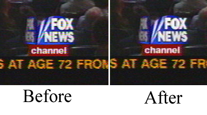
If you have vertical blanking information or crawls which constantly change in each frame, block them out with the Mask tool. This improves compression ratios.
This is about all you can do without destroying more data than you would naturally lose in compression. The more invasive cleaning techniques involve deinterlacing.
Next: MAKING VIDEO LOOK LIKE FILM, Previous: ANALOG TV CLEANING, Up: APPLICATION NOTES [Contents]
Interlacing is done on most video sources because it costs too much to build progressive scanning cameras and progressive scanning CRT’s. Many a consumer has been disappointed to spend 5 paychecks on a camcorder and discover what horrible jagged images it produces on a computer monitor.
As for progressive scanning camcorders, forget it. Cost factors are probably going to keep progressive scanning cameras from ever equalling the spatial resolution of interlaced cameras. Interlacing is here to stay. That’s why they made deinterlacing effects in Cinelerra.
We don’t believe there has ever been a perfect deinterlacing effect. They’re either irreversible or don’t work. Cinelerra cuts down the middle by providing deinterlacing tools that are irreversible sometimes and don’t work sometimes but are neither one or the other.
Line Doubling
This one is done by the Deinterlace effect when set to Odd lines or Even lines. When applied to a track it reduces the vertical resolution by 1/2 and gives you progressive frames with stairstepping. This is only useful when followed by a scale effect which reduces the image to half its size.
Line averaging
The Deinterlace effect when set to Average even lines or Average odd lines does exactly what line doubling does except instead of making straight copies of the lines it makes averages of the lines. This is actually useful for all scaling.
There’s an option for adaptive line averaging which selects which lines to line average and which lines to leave interlaced based on the difference between the lines. It doesn’t work.
Inverse Telecine
This is the most effective deinterlacing tool when the footage is an NTSC TV broadcast of a film. See INVERSE TELECINE.
Time base correction
The first three tools either destroy footage irreversibly or don’t work sometimes. Time base correction is last because it’s the perfect deinterlacing tool. It leaves the footage intact. It doesn’t reduce resolution, perceptually at least. It doesn’t cause jittery timing.
The Frames to Fields effect converts each frame to two frames, so it must be used on a timeline whose project frame rate is twice the footage’s frame rate. In the first frame it puts a line averaged copy of the even lines. In the second frame it puts a line averaged copy of the odd lines. When played back at full framerates it gives the illusion of progressive video with no loss of detail.
Best of all, this effect can be reversed with the Fields to frames effect. That one combines two frames of footage back into the one original interlaced frame of half the framerate.
Be aware that frames to fields inputs frames at half the framerate as the project. Effects before frames to fields process at the reduced framerate.
Unfortunately, the output of Frames to Fields can’t be compressed as efficiently as the original because it introduces vertical twitter and a super high framerate.
Interlaced 29.97fps footage can be made to look like film by applying Frames to Fields and then reducing the project frame rate of the resulting 59.94fps footage to 23.97fps. This produces no timing jitter and the occasional odd field gives the illusion of more detail than there would be if you just line averaged the original.
HDTV exceptions
1920x1080 HDTV is encoded a special way. If it’s a broadcast of original HDTV film, an inverse telecine works fine. If it’s a rebroadcast of a 720x480 source, you need to use a time base and line doubling algorithm to deinterlace it, See 1080 TO 480.
Next: CLEARING OUT HAZE, Previous: DEFEATING INTERLACING, Up: APPLICATION NOTES [Contents]
Video sweetening is constantly getting better. Lately the best thing you can do for dirt cheap consumer camcorder video is to turn it into progressive 24fps output. While you can’t really do that, you can get pretty close for the money. Mind you, this procedure can degrade high quality video just as easily as it improves low quality video. It should only be used for low quality video.
This entire procedure could be implemented in one nonrealtime effect, but the biggest problem with that is you’ll most often want to keep the field based output and the 24fps output for posterity. A nonrealtime effect would require all that processing just for the 24fps copy. Still debating that one.
Next: MAKING A DVD, Previous: MAKING VIDEO LOOK LIKE FILM, Up: APPLICATION NOTES [Contents]
Let’s face it, if you’re employed you live in Silicon Valley. As such you probably photograph a lot of haze and never see blue sky ever. Even if you can afford to briefly go somewhere where there is blue sky, horizon shots usually can stand for more depth. This is what the gradient effect is for.
Drop the gradient effect on hazy tracks. Set the following parameters:
Angle: 0
Inner radius: 0
Outer radius: 40
Inner color: blue 100% alpha
Outer color: blue 0% alpha
It’s important to set the 0% alpha color to blue even though it’s 0% alpha. The color of the outer alpha is still interpolated with the inner color. This is a generally applicable setting for the gradient. Some scenes may work better with orange or brown for an evening feel.
Next: MAKING A RINGTONE, Previous: CLEARING OUT HAZE, Up: APPLICATION NOTES [Contents]
A single chapter DVD
Make a single chapter DVD by rendering video to an MPEG video file. The video should be 720x480, 29.97fps. The aspect ratio should be 16x9 or 4x3.
Use the YUV 4:2:0 color model and DVD preset. Set the bitrate to the desired bitrate. It’s not clear exactly what other parameters the MPEG encoder uses in the DVD preset but we’ve enabled the following:
Derivative: MPEG-2
Fixed bitrate
I frame distance: 15
P frame distance: 0
Sequence start codes in every GOP
Render the audio to an AC3 audio file. Any bitrate can be used.
Dvdrtools must be downloaded to generate the actual DVD filesystem. The actual usage of dvdrtools changes frequently but currently it involves the mkisofs and ifogen programs. Mkisofs is built automatically in dvdrtools but ifogen may have to be built manually by entering the video directory and running make ifogen. Mkisofs and ifogen must be put into /usr/bin manually.
Also, the mplex program from mjpegtools must be installed. The mjpegtools package is built in the hvirtual distribution and the mplex utility may be extracted from there.
Given the files audio.ac3 and video.m2v, rendered by Cinelerra, the following commands pack them into a dvd readable by commercial appliances.
mplex -M -f 8 -o final.mpg audio.ac3 video.m2v
mkdir -p dvd/VIDEO_TS
ifogen final.mpg -o dvd
ifogen -T -o dvd
mkisofs -dvd-video -udf -o dvd.iso dvd/
Chapters may be set with the following. The units are seconds. Version 0.3.1 ignores the 1st chapter, so it has to be specified as 0.
ifogen -o dvd --chapters=0,0021.788,0047.447,0077.043 final.mpg
Replace the chapter times.
dvd.iso can be burned directly to a DVD with the following:
dvdrecord -ignsize -dao -v dev=/dev/hdc fs=67108864 dvd.iso
The argument to dev= is the IDE device of the DVD drive. Burning DVD’s through SCSI is currently not supported.
Next: TIME STRETCHING AUDIO, Previous: MAKING A DVD, Up: APPLICATION NOTES [Contents]
This is how we made ringtones for the low end Motorola V180’s and it’ll probably work with any new phone. Go to File->Load files... and load a sound file with Insertion strategy: Replace current project. Go to Settings->Format change Channels to 1 and Samplerate to 16000 or 22050.
Either highlight a region of the timeline or set in/out points to use for the ringtone. To improve sound quality on the cell phone, you need the maximum amplitude in as many parts of the sound as possible. Right click on track Audio 1 and select Attach effect... Highlight the Compressor effect and hit Attach in the attachment popup.
Make sure the insertion point or highlighted area is in the region with
the Compressor effect. Right click on track Audio 2 and select
Attach effect... Highlight Audio 1: Compressor and hit
Attach. Click the Audio1 Compressor’s magnifying glass
to bring up the compressor GUI.
Set the following parameters:
Reaction secs: -0.1
Decay secs: 0.1
Trigger Type: Total
Trigger: 0
Smooth only: No
Click Clear to clear the graph. Click anywhere in the grid area and drag a new point to 0 Output and -50 Input. The graph should look like this.
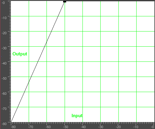
Go to File->Render. Specify the name of an mp3 file to output to.
Set the file format to MPEG Audio. Click the wrench
for Audio and set Layer to III and Kbits per second to
24 or 32. Check Render audio tracks and uncheck Render
video tracks. Hit OK to render the file.
The resulting .mp3 file must be uploaded to a web server. Then, the phone’s web browser must download the .mp3 file directly from the URL. There also may be a size limit on the file.
Next: PITCH SHIFTING AUDIO, Previous: MAKING A RINGTONE, Up: APPLICATION NOTES [Contents]
It may appear that time stretching audio is a matter of selecting a region of the audio tracks, enabling recording for the desired tracks, going to Audio->Render Effect, and applying Time Stretch. In actuality there are 3 audio effects for time stretching: Time Stretch, Resample, and Asset info dialog.
Time Stretch applies a fast fourier transform to try to change the duration without changing the pitch, but this introduces windowing artifacts to the audio. It’s only useful for large changes in time because obvious changes in duration make windowing artifacts less obtrusive.
For smaller changes in duration, in the range of 5%, Resample should be used. This changes the pitch of the audio but small enough changes aren’t noticable. Resample doesn’t introduce any windowing artifacts, so this is most useful for slight duration changes where the listener isn’t supposed to know what’s going on.
Another way to change duration slightly is to go to the Resources window, highlight the media folder, right click on an audio file, click on Info. Adjust the sample rate in the Info dialog to adjust the duration. This method also requires left clicking on the right boundary of the audio tracks and dragging left or right to correspond to the length changes.
Next: TEXT TO MOVIE, Previous: TIME STRETCHING AUDIO, Up: APPLICATION NOTES [Contents]
Like the time stretching methods, there are three pitch shifting methods: Pitch shift, Resample, and Asset info dialog. Pitch shift is a realtime effect which can be dragged and dropped onto recordable audio tracks. Pitch shift uses a fast fourier transform to try to change the pitch without changing the duration, but this introduces windowing artifacts.
Because the windowing artifacts are less obtrusive in audio which is obvously pitch shifted, Pitch shift is mainly useful for extreme pitch changes. For mild pitch changes, use Resample from the Audio->Render Effect interface. Resample can change the pitch within 5% without a noticable change in duration.
Another way to change pitch slightly is to go to the Resources window, highlight the media folder, right click on an audio file, click on Info. Adjust the sample rate in the Info dialog to adjust the pitch. This method also requires left clicking on the right boundary of the audio tracks and dragging left or right to correspond to the length changes.
Previous: PITCH SHIFTING AUDIO, Up: APPLICATION NOTES [Contents]
Text to movie was added when another one of those startups whose name was an unmemorable combination of farting noises that the venture capitalist heard, started charging money for a ridulously simple program that converted scripts directly to movies. It was such a simple program, we decided to add most of the functionality to Cinelerra.
The easiest way to make a movie is to copy tests/text2movie and tests/text2movie.xml as a starting point. Load the text2movie.xml file to see the movie.
The text2movie file acts like a normal asset, except changes to it are immediately reflected on the timeline, without reloading. Also, the length is infiinite. Edit the text2movie file to change the script. If the length of the movie increases, drag the right edit handle to extend the edit or use edit->edit length.
1 audio channel is created for every character. The frame rate, sample rate, and frame size are fixed. Get it from the asset window. Right click on the asset and go to Asset info... Camera angles are fixed.
Since its only use was to show dialog between 2 people, that’s the functionality we focused on. The character model and voice is selected separately in the script, because that was how it was done with the fee service. The models are defined in model files, in the Cinelerra executable directory. Usually /opt/cinelerra/models.
There is a search path for models, starting with the directory the script is in. You can define new models for the script, without affecting the entire system. The model files are the exact name that appears in the script. They define the total size of the model and the images used in the model.
The models are 2D png images, because all the animations are baked. No custom movement is currently supported, that would require a 3D renderer.
Some actions are implemented. Character2 can cut off character1 if character1’s dialog ends in ...
Inserting [pause] anywhere causes the character to pause. Useful for adjusting the timing of dialog.
Speech synthesis is pretty lousy. Punctuation and spelling needs to be adjusted based on the sound. The dialog is rendered on-demand, so there is a delay when each character starts to speak. Split dialog into shorter blocks to reduce the delay.
Next: PLUGIN AUTHORING, Previous: APPLICATION NOTES, Up: TOP [Contents]
Most effects in Cinelerra can be figured out just by using them and tweaking. Here are brief descriptions of effects which you might not utilize fully by mere experimentation.
| • 1080 TO 480: | How to convert HDTV into SD | |
| • BACKGROUND: | Replacing transparency with rendered backgrounds | |
| • BLUR: | Blur | |
| • CHROMA KEYERS: | Create transparency based on color. | |
| • COLOR SWATCH: | Color swatch | |
| • COMPRESSOR: | How to reduce the dynamic range of audio. | |
| • MULTIBAND COMPRESSOR: | Reduce the dynamic range of audio by frequency range. | |
| • DECIMATE: | How to reduce frame rates by eliminating similar frames. | |
| • DEINTERLACE: | How to convert interlaced video to progressive video. | |
| • DIFFERENCE KEY: | Create transparency based on color differences. | |
| • FIELDS TO FRAMES: | How to recover interlaced video from bobbed video | |
| • FREEZE FRAME: | How to stop action in the timeline. | |
| • HISTOGRAM: | How to change the mapping of different brightness values. | |
| • INVERSE TELECINE: | How to convert pulled down frames to progressive frames. | |
| • INTERPOLATE VIDEO: | How to create the illusion of higher framerates. | |
| • LENS: | Correcting spherical aberration | |
| • LINEARIZE: | Fix gamma in raw camera images | |
| • LIVE AUDIO: | Pass audio from the soundcard directly to the timeline. | |
| • LIVE VIDEO: | Pass video from the capture card directly to the timeline. | |
| • LOOP: | How to loop regions of the timeline. | |
| • LUT: | Color processing with look up tables | |
| • MOTION EFFECTS: | Stabilizing & tracking motion | |
| • REFRAMERT: | Changing the number of frames in a sequence. | |
| • REFRAME: | Changing the number of frames in a sequence with rendering. | |
| • RESAMPLE: | Change the number of samples in a sequence with rendering. | |
| • REVERSE VIDEO/AUDIO: | How to play regions in reverse. | |
| • SWAP FRAMES: | Fixing temporal field order | |
| • SWAP CHANNELS: | Route color channels to different channels & tracks | |
| • THRESHOLD: | How to get monochrome out of a region of the image. | |
| • TIME AVERAGE: | How to stack images. | |
| • TIME FRONT: | Select pixels to display based on time | |
| • TITLER: | How to add text to a track from inside Cinelerra. | |
| • VIDEO SCOPE: | How to view the dynamic range of intensity and hue. |
Next: BACKGROUND, Up: EFFECTS NOTES [Contents]
Most TV broadcasts are received with a 1920x1080 resolution but originate from a 720x480 source at the studio. It’s a waste of space to compress the entire 1920x1080 if the only resolvable details are 720x480. Unfortunately resizing 1920x1080 video to 720x480 isn’t as simple as shrinking it.
At the TV station the original 720x480 footage was first converted to fields of 720x240. Each field was then scaled up to 1920x540. The two 1920x540 fields were finally combined with interlacing to form the 1920x1080 image. This technique allows a consumer TV to display the resampled image without extra circuitry to handle 720x480 interlacing in a 1920x1080 image.
If you merely deinterlaced the 1920x1080 images, you would end up with resolution of 720x240. The 1080 to 480 effect properly extracts two 1920x540 size fields from the image, resizes them separately, and combines them again to restore a 1920x480 interlaced image. The scale effect must then be applied to reduce the horizontal size to 960 or 720 depending on the original aspect ratio.
The tracks to which 1080 to 480 is applied need to be at 1920x1080 resolution. The project settings in settings->format should be at least 720x480 resolution.
The effect doesn’t know if the first row in the 1920x1080 image belongs to the first row of the 720x480 original. You have to specify what the first row is in the effect configuration.
The output of this effect is a small image in the middle of the original 1920x1080 frame. Use the projector to center the output image in the playback.
Finally, once you have 720x480 interlaced video you can either apply frames to fields of inverse telecine to further recover original progressive frames.
Next: BLUR, Previous: 1080 TO 480, Up: EFFECTS NOTES [Contents]
This creates either a flat color or a color cube for use with the LUT (See LUT) effect. Use it to fill transparent areas with a custom color. The color cube option is drawn in a fixed part of the frame to aid in creating a LUT.
Next: CHROMA KEYERS, Previous: BACKGROUND, Up: EFFECTS NOTES [Contents]
Applies a gaussian blur. Changing the horizontal value changes the horizontal blurring. Changing the vertical value changes the vertical blurring. Enabling lock causes the values to be the same.
Alpha determines radius causes higher alpha to blur more & all the output alpha to be set to maximum. This is used for fake tilt shift, fake depth of field, & hiding sections of the image.
Next: COLOR SWATCH, Previous: BLUR, Up: EFFECTS NOTES [Contents]
| • CHROMA KEY: | ||
| • CHROMAKEY HSV: |
Next: CHROMAKEY HSV, Up: CHROMA KEYERS [Contents]
This was the 1st chroma keyer. It erases pixels which are near the selected color in the RGB color cube. It uses the same algorithm as the Gimp selection tools. It works best with computer generated graphics.
Colors are replaced with black if there is no alpha channel and transparency if there is an alpha channel. The selection of color model is important to determine the behavior.
Chroma key uses either the lightness or the hue to determine what is erased. Use value singles out only the lightness to determine transparency. Select a center color to erase using the Color button. Alternatively a color can be picked directly from the output frame by first using the color picker in the compositor window and then selecting the Use color picker button. This sets the chroma key color to the current color picker color.
Be aware that the output of the chroma key is fed back to the compositor, so selecting a color again from the compositor will use the output of the chroma key effect. The chroma key should be disabled when selecting colors with the color picker.
If the lightness or hue is within a certain threshold it’s erased. Increasing the threshold determines the range of colors to be erased. It’s not a simple on/off switch, however. As the color approaches the edge of the threshold, it gradually gets erased if the slope is high or is rapidly erased if the slope is low. The slope as defined here is the number of extra values flanking the threshold required to go from opaque to transparent.
Normally threshold is very low when using a high slope. The two parameters tend to be exclusive because slope fills in extra threshold.
The slope tries to soften the edges of the chroma key but it doesn’t work well for compressed sources. A popular softening technique is to use a maximum slope and chain a blur effect below the chroma key effect to blur just the alpha.
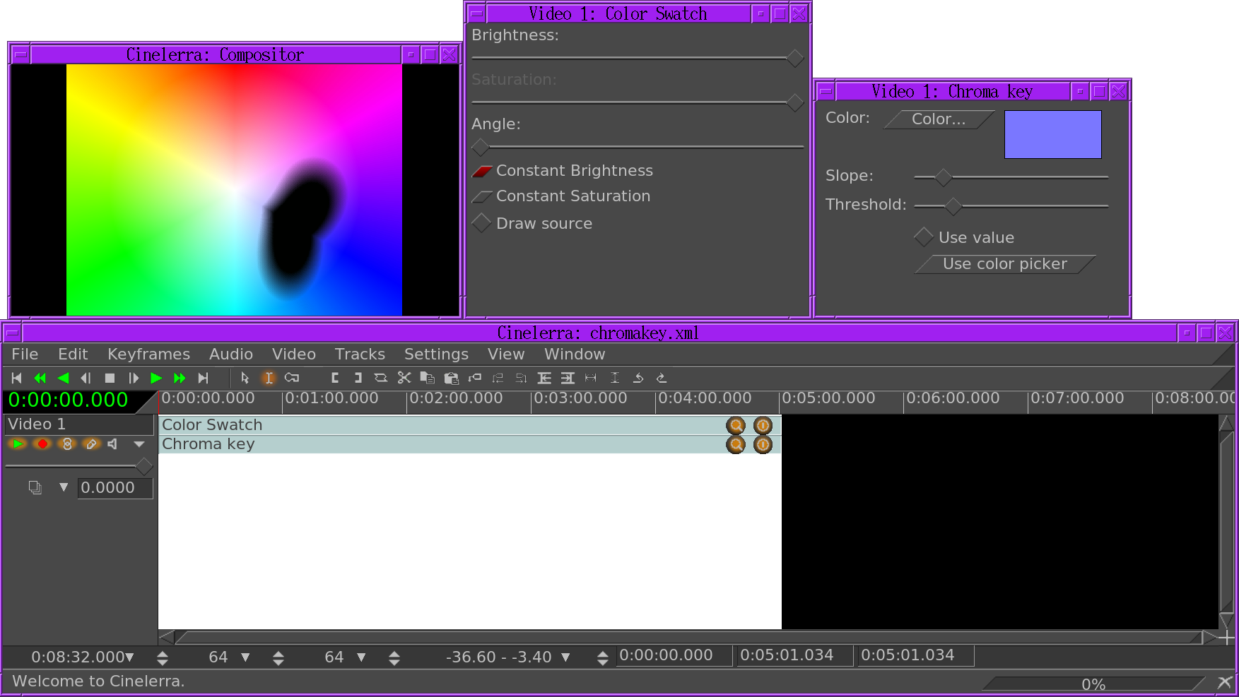
Previous: CHROMA KEY, Up: CHROMA KEYERS [Contents]
This chroma keyer is a rough replica of the Avid Spectra Matte. It creates a superior key for video camera sources. The best way to visualize the effect is to attach a Color Swatch to the source footage, then Chroma Key HSV. Set the brightness & saturation in the color swatch to 100 for easiest visualization. In Chroma Key HSV, set the alpha offset to 0, min brightness to 0, max brightness to 100 for easiest visualization.
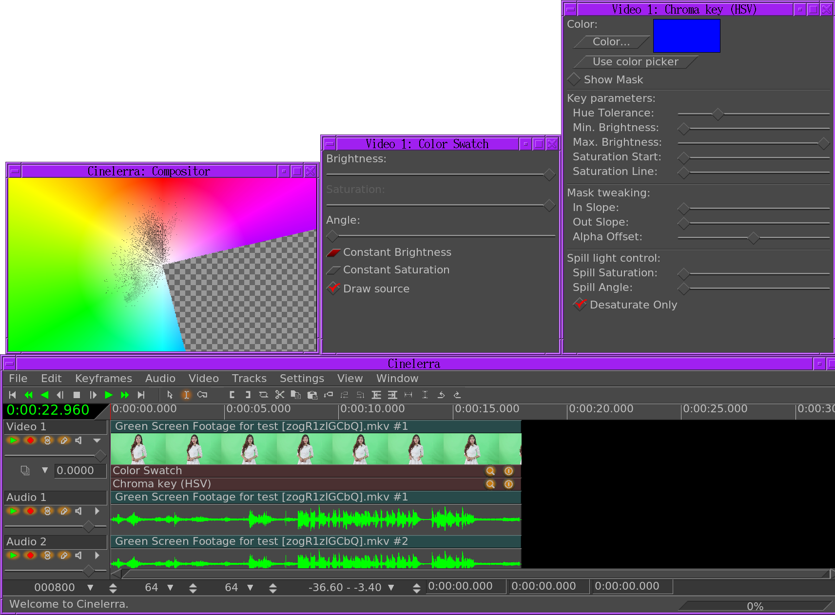
To visualize how much of the source is being taken out, set the color swatch to draw source. This draws pixels in the color swatch that are in the source.
Chroma Key HSV creates a transparent wedge in the color swatch.
The position of the wedge starts with the hue selected by color. The saturation & value in the color are ignored & should be maximum for the most accuracy. Only the hue is used.
Use color picker copies the data in the compositor’s color picker to the starting color.
Show mask replaces the non transparent area with white.
KEY PARAMETERS
The next parameters grow the starting color into a wedge & modify it.
Hue tolerance An angle that determines how wide the wedge is. This must be between 0 & 45 to get an intuitive shape.
Min brightness, max brightness determine the range of brightnesses the wedge appears in. If the color swatch is in constant saturation, the brightness range determines the start & end radius of the wedge. If the color swatch is in constant brightness, the brightness range cuts off the wedge as you slide around the color swatch brightness value. For the best experience when experimenting, set min & max brightness to 0 & 100.
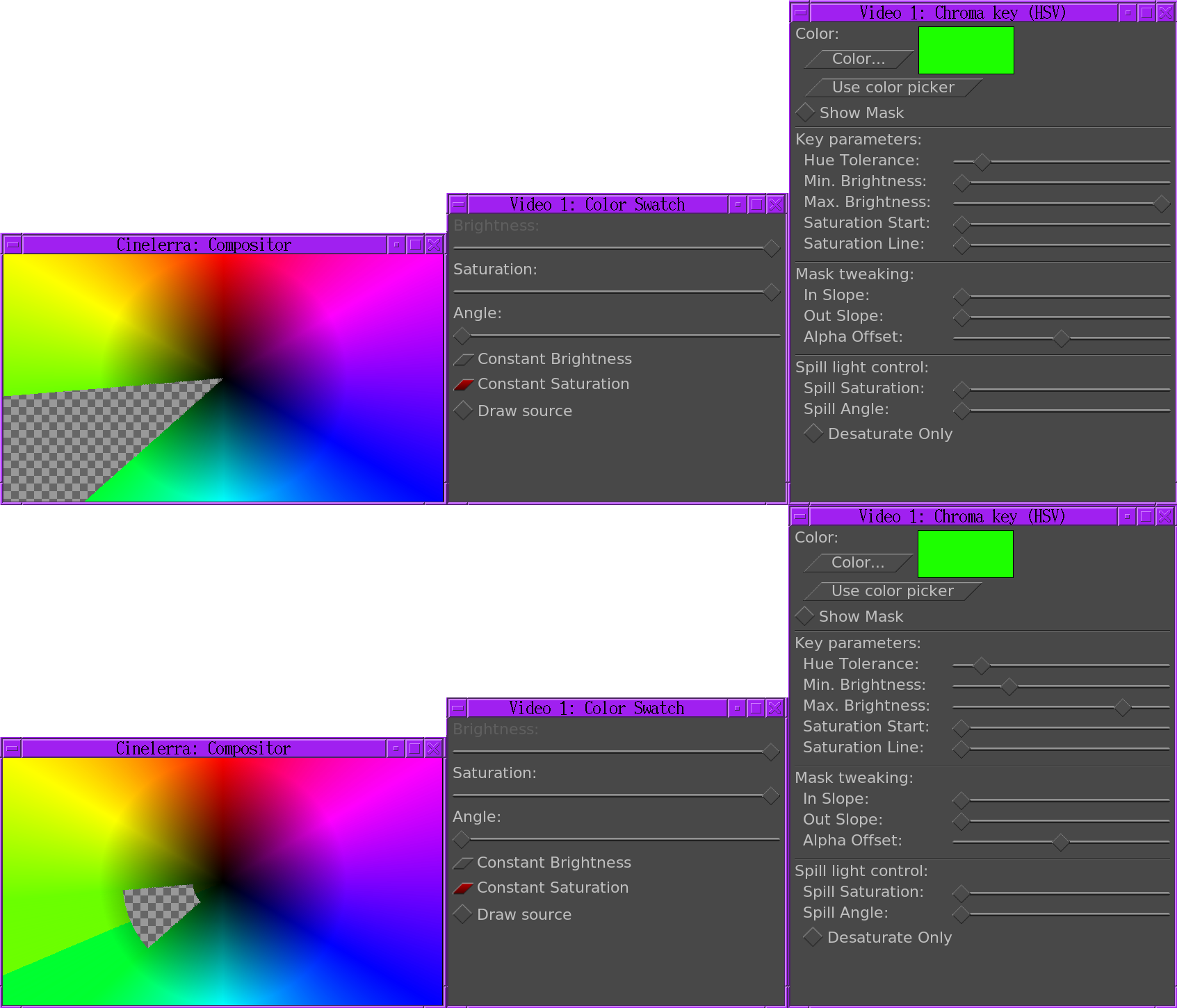
Saturation start determines the radius of the point of the wedge when the color swatch is in constant brightness.
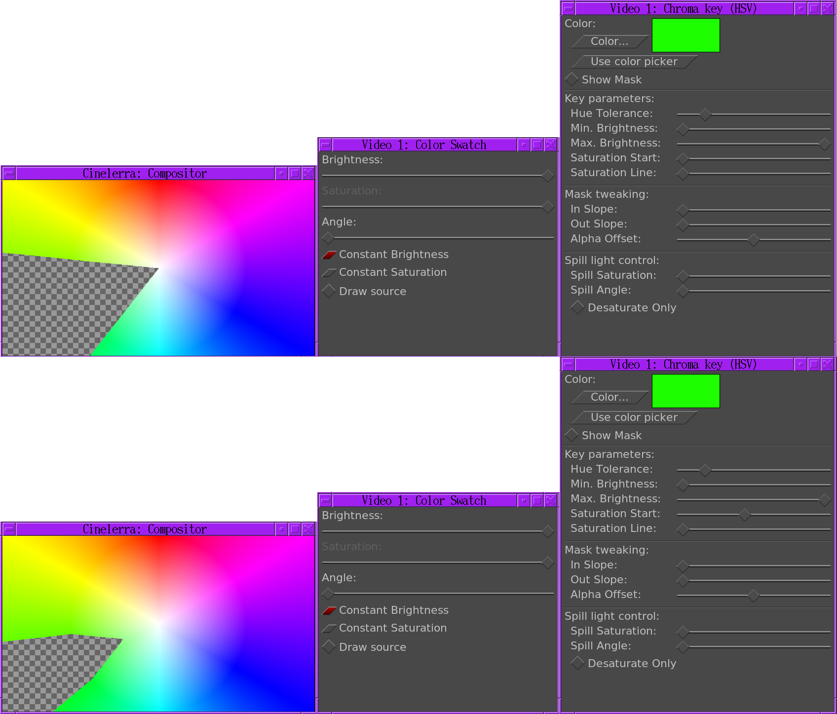
Saturation line is an additional radius which is taken out of the wedge.
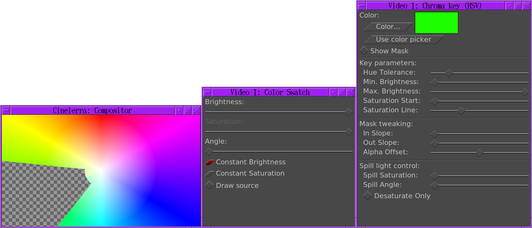
MASK TWEEKING
In slope takes transparent area out of the wedge using a gradient
Out slope adds transparent area to the wedge using a gradient
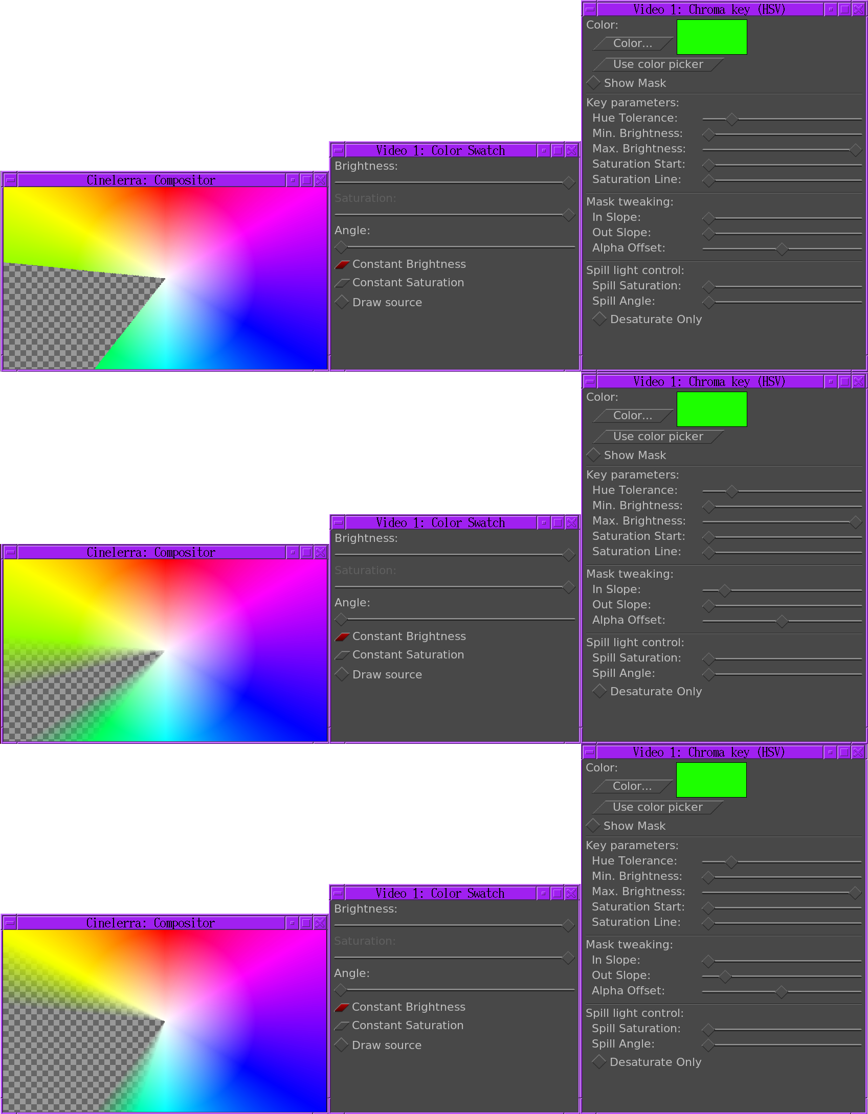
Alpha offset When greater than 0, this fills in the wedge with a constant alpha. When less than 0, this takes a constant alpha out of the opaque part of the color swatch. For the best experience when experimenting, set it to 0.
SPILL LIGHT CONTROL
The spill light control tries to remove light reflected by the green screen onto the subject. The idea is to eliminate colors bordering the wedge without making them transparent. The spill light control is always applied as a gradient, based on the behavior of the Avid effect.
Spill saturation This adds a minimum saturation below the saturation start at which to begin taking out spill light. To visualize this, the color swatch should be in constant brightness. Saturation start should be greater than 0. Increasing spill saturation rewinds from the wedge point & begins replacing colors from the rewound point.
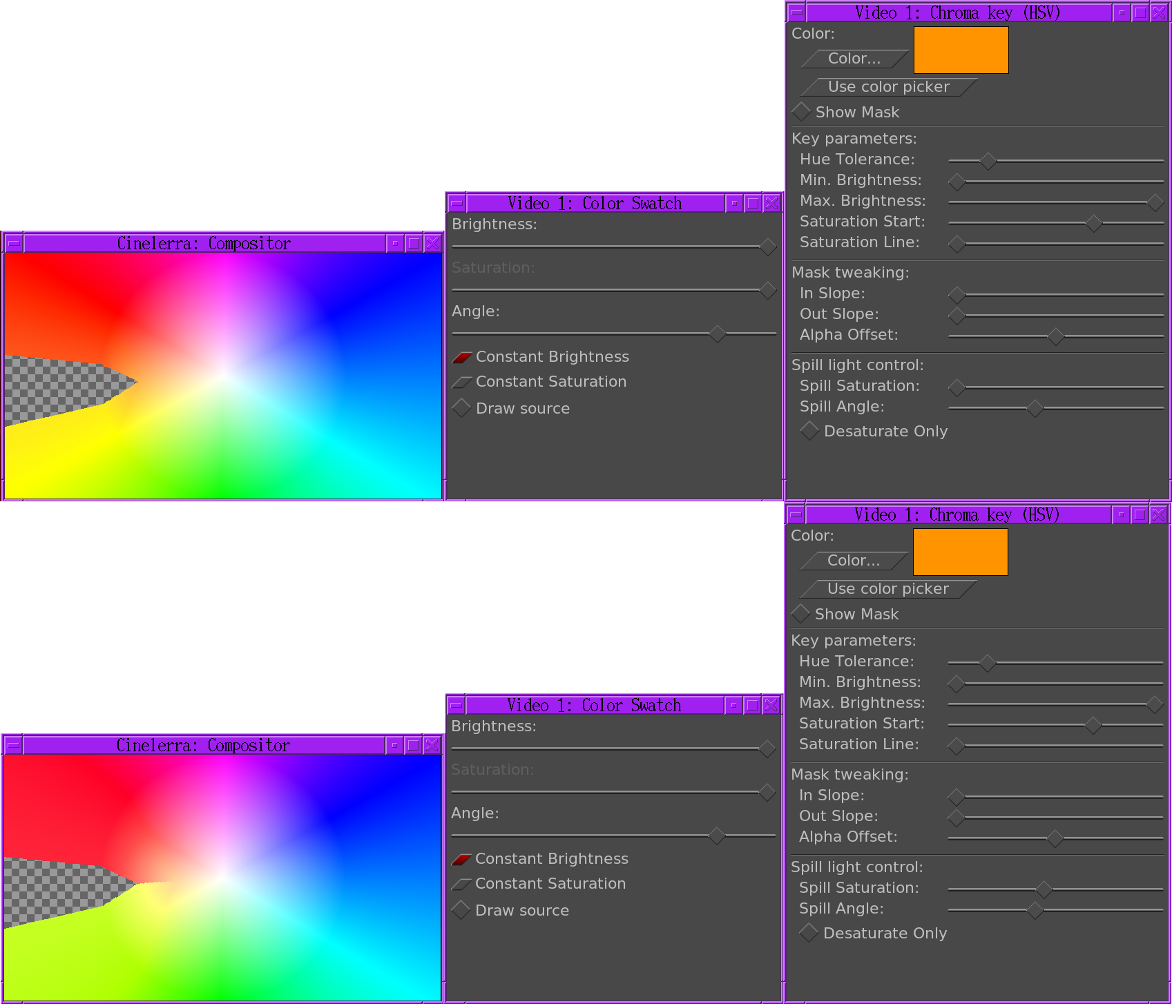
Spill angle An angle added to the hue tolerance to make the wedge wider. Inside this angle, a constant hue is copied from the neighboring part of the color swatch to the area where the spill light would be. Increase the spill angle to copy hue from farther away from the wedge.
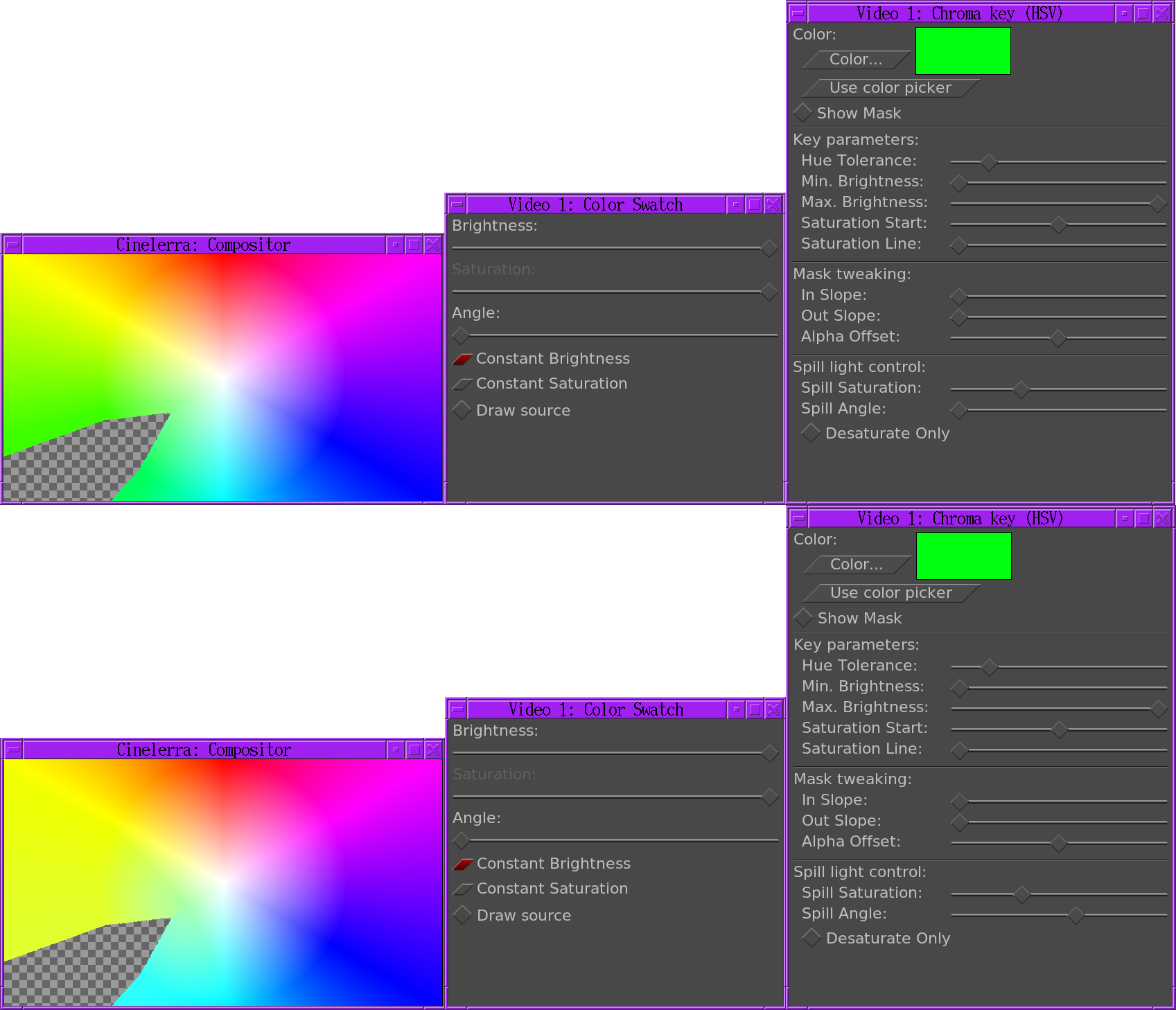
Desaturate only Instead of copying the neighboring hue in the color swatch, this takes all the color out, yielding white where the spill light would be. This was the behavior of chromakey HSV when it was 1st ported to Cinelerra but is not the Avid behavior.

Next: COMPRESSOR, Previous: CHROMA KEYERS, Up: EFFECTS NOTES [Contents]
This draws the entire color space for a fixed saturation or brightness. It’s mainly used for testing chroma keying by providing an input to chroma keying.
constant brightness draws the color space for a fixed brightness. The brightness slider changes the brightness.
constant saturation draws the color space for a fixed saturation. The saturation slider changes the saturation.
angle rotate the color space to line up with another document or interface.
draw source draws the pixels in the source in the swatch with the brightness or saturation they had in the source. This shows how much of the source is being taken out by a chroma key & where the source occurs in the color space.
Next: MULTIBAND COMPRESSOR, Previous: COLOR SWATCH, Up: EFFECTS NOTES [Contents]
The audio compressor reduces or expands the dynamic range of the audio. In Cinelerra the compressor actually performs the function of an expander and compressor.
The compressor works by calculating the maximum sound level within a certain time period of the current position. The maximum sound level is taken as the trigger value. For every trigger value there is an output sound level specified by the user. The gain at the current position is adjusted so the maximum sound level in the time range is the user specified output value.
The compressor has a graph which correlates every trigger sound level to an output level. The horizontal direction is the trigger sound level in dB. The vertical direction is the output sound level in dB. The user specifies output sound levels by creating points on the graph. Click in the graph to create a point. If 2 points exist, drag one point across another point to delete it. The most recent point selected has its vales displayed in OUTPUT INPUT textboxes for more precise adjustment.
Right click in the graph to get a context menu.
copy graph copies the graph to the clipboard. It may be pasted in a text editor for editing & copied from the text editor.
past graph to paste the clipboard in the graph. This allows graphs to be copied between band in the multiband compressor.
clear graph erases all the points.
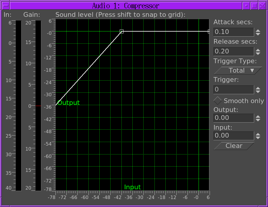
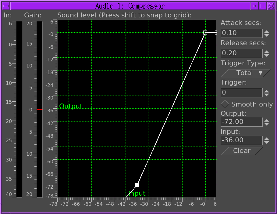
To make the compressor reduce the dynamic range of the audio, make all the output values greater than the input values except 0 db. To make the compressor expand the dynamic range of the audio, make all the output values except 0 db less than the input values. The algorithm currently limits all sound levels above 0 db to 0 db so to get an overloaded effect put a gain effect before the compressor to reduce all the levels and follow it with another gain effect to amplify all the levels back over 0 db.
Reaction secs: This determines where in relation to the current position the maximum sound level is taken and how fast the gain is adjusted to reach that peak. It’s notated in seconds. If it’s negative the compressor reads ahead of the current position to get the future peak. The gain is ramped to that peak over one reaction time. This allows it to hit the desired output level exactly when the input peak occurs at the current position.
If the reaction time is positive the compressor scans only the current position for the gain and ramps gain over one reaction time to hit the desired output level. It hits the output level exactly one reaction time after detecting the input peak.
Decay secs: If the peak is higher than the current level, the compressor ramps the gain up to the peak value. Then if a future peak is less than the current peak it ramps the gain down. The time taken to ramp the gain down can be greater than the time taken to ramp the gain up. This ramping down time is the decay seconds.
Trigger type: The compressor is a multichannel effect. Several tracks can share one compressor. How the signal from many tracks is interpreted is determined by the trigger type.
The Trigger trigger type uses the value supplied in the Trigger textbox as the number of the track to use as input for the compressor. This allows a track which isn’t even heard to determine the loudness of the other tracks.
The Maximum trigger takes the loudest track and uses it as the input for the compressor.
The Total trigger type adds the signals from all the tracks and uses the total as the input for the compressor. This is the most natural sounding compression and is ideal when multiple tracks are averaged into single speakers.
Trigger: The compressor is a multichannel effect. Several tracks can share one compressor. Normally only one track is scanned for the input peak. This track is specified by the Trigger. By sharing several tracks and playing with the trigger value, you can make a sine wave on one track follow the amplitude of a drum on another track for example.
Envelope: This replaces the output waveform with just the current trigger value. It allows visualizing what the compressor is doing to the soundlevel. It makes it very easy to see how reaction secs affects the detected peak values. The envelope output can also be used as a control value in another effect.
IN: This meter shows the current value of the trigger during playback.
GAIN: This meter shows what gain is being computed from the trigger. If it’s above 0, the input is being amplified. If it’s below 0, the input is being reduced.
Next: DECIMATE, Previous: COMPRESSOR, Up: EFFECTS NOTES [Contents]
This adds more features to the compressor for individually compressing different frequency bands. There are 3 bands, each with its own sound level graph. Use the context menu in the graph to copy curves from 1 band to another or a text editor.
The same attack, release, trigger type, trigger, envelope, window size apply to all 3 bands.
CURRENT BAND Select the current band to show in the graph.
SOLO BAND Mutes the other bands & only plays the band selected. The solo band for the other bands is automatically deselected when this is selected.
BYPASS BAND Disregards the graph for the current band & passes the audio through. The frequency range is still applied.
FREQ RANGE The multiband compressor has 3 frequency ranges which may not overlap. The frequency range shows 2 of the 3 border frequencies at a time.
For band 1, the frequency range shows only the maximum frequency of the low range.
For band 2, the frequency range shows the maximum frequency of the low range & the minimum frequency of the high range.
For band 3, the frequency range shows the minimum frequency of the high range.
BANDWIDTH This is only a visual representation of the 3 bands & the spectrum of the current audio. It doesn’t take any inputs.
STEEPNESS This is how steep the transitions between the bands are.
WINDOW SIZE This determines the size of the FFT that creates the frequency bands. The higher it is, the more precise the filter but the more it has to read ahead. Higher steepness requires a higher window size to truly be realized.
Next: DEINTERLACE, Previous: MULTIBAND COMPRESSOR, Up: EFFECTS NOTES [Contents]
This effect drops frames from a track which are most similar in order to reduce the frame rate. This is usually applied to a DVD to convert the 29.97 fps video to the 23.97 fps film rate but this decimate effect can take any input rate and convert it to any lower output rate.
The output rate of decimate is the project frame rate. The input rate is set in the decimate user interface. To convert 29.97fps progressive video to 23.97fps film, apply a decimate effect to the track. Set the decimate input rate to 29.97 and the project rate to 23.97.
Be aware every effect layered before decimate processes video at the decimate input rate and every effect layered after decimate processes video at the project frame rate. Computationally intensive effects should come below decimate.
Next: DIFFERENCE KEY, Previous: DECIMATE, Up: EFFECTS NOTES [Contents]
The deinterlace effect has evolved over the years to deinterlacing and a whole lot more. In fact two of the deinterlacing methods, Inverse Telecine and Frames to Fields, are separate effects. The deinterlace effect offers several variations of line replication to eliminate comb artifacts in interlaced video. It also has some line swapping tools to fix improperly captured video or make the result of a reverse effect display fields in the right order.
Next: FIELDS TO FRAMES, Previous: DEINTERLACE, Up: EFFECTS NOTES [Contents]
The differency key creates transparency in areas which are similar between 2 frames. The Difference key effect must be applied to 2 tracks. One track contains the action in front of a constant background and another track contains the background with nothing in front of it. Apply the difference key to the track with the action and apply a shared copy of it to the track with the background. The track with the background should be muted and underneath the track with the action and the colormodel should have an alpha channel.
Pixels which are different between the background and action track are treated as opaque. Pixels which are similar are treated as transparent. Change threshold in the differency key window to make more pixels which aren’t the same color transparent. Change slope to change the rate at which the transparency tapers off as pixels get more different.
The slope as defined here is the number of extra values flanking the threshold required to go from opaque to transparent. A high slope is more useful with a low threshold because slope fills in extra threshold.
Use value causes the intensity of pixels to be compared instead of the color.
Applying a blur to the top track with just the alpha channel blurred can soften the transparency border.
Next: FREEZE FRAME, Previous: DIFFERENCE KEY, Up: EFFECTS NOTES [Contents]
This effects reads frames at twice the project framerate, combining 2 input frames into a single interlaced output frame. Effects preceding fields to frames process frames at twice the project frame rate. Each input frame is called a field.
Fields to frames needs to know what field corresponds to what lines in the output frame. The easiest way to figure it out is to try both options in the window. If the input fields are the result of a line doubling process like frames to fields, the wrong setting results in blurrier output. If the input fields are the result of a standards conversion process like 1080 to 480, the wrong setting won’t make any difference.
The debobber which converts 720x480 interlaced into 1920x1080 interlaced or 1280x720 progressive seems to degrade the vertical resolution to the point that it can’t be recovered.
Next: HISTOGRAM, Previous: FIELDS TO FRAMES, Up: EFFECTS NOTES [Contents]
In its simplest form, highlight a region of the track to freeze, drop the freeze frame effect on the highlighted region, and the lowest numbered frame in the affected area will play throughout the entire region.
Freezeframe has an enabled option which can be keyframed. Regions of a freeze frame effect which are enabled repeat the lowest numbered frame since the last keyframe. This has unique possibilities.
If a freeze frame effect has a keyframe in the middle of it set to enabled, the frame in the middle is repeated in the entire effect.
If a freeze frame effect has several keyframes, each set to enabled, every time a keyframe is encountered the frame under it becomes the frozen one.
If a freeze frame effect alternates between enabled and disabled, each time an enabled keyframe is encountered the frame under it is replicated until the next disabled keyframe. The disabled regions play through.
Next: INVERSE TELECINE, Previous: FREEZE FRAME, Up: EFFECTS NOTES [Contents]
This shows the number of occurrences of each color on a histogram plot.
It is always performed in floating point RGB regardless of the project colorspace. The histogram has two sets of transfer parameters: the input transfer and the output transfer.
4 histograms are possible in the histogram viewer. The red, green, blue histograms show the input histograms for red, green, blue and multiply them by an input transfer to get the output red, green, blue. Then the output red, green, blue is scaled by an output transfer. The scaled red, green, blue is converted into a value and plotted on the value histogram. The value histogram thus changes depending on the settings for red, green, blue. The value transfers are applied uniformly to R, G, B after their color transfers are applied.
Select which transfer to view by selecting one of the channels on the top of the histogram.
The input transfer is defined by a graph overlaid on the histogram. The horizontal direction corresponds to every possible input color. The vertical direction corresponds to the output color for every input color. Video entering the histogram is first plotted on the histogram plot, then it is translated so output values now equal the output values for each input value on the input graph.
The input graph is edited by adding and removing any number of points. Click and drag anywhere in the input graph to create a point and move it. Click on an existing point to make it active and move it. The active point is always indicated by being filled in. The active point’s input and output color are given in text boxes on top of the window. The input and output color of the point can be changed through these text boxes.
Points can be deleted by first selecting a point and then dragging it to the other side of an adjacent point. They can also be deleted by selecting them and hitting delete.
After the input transfer, the image is processed by the output transfer. The output transfer is simply a minimum and maximum to scale the input colors to. Input values of 100% are scaled down to the output’s maximum. Input values of 0% are scaled up to the output minimum.
Input values below 0 are always clamped to 0 and input values above 100% are always clamped to 100%. Click and drag on the output gradient’s triangles to change it. It also has textboxes to enter values into.
Enable the automatic toggle to have the histogram calculate an automatic input transfer for the red, green, blue but not the value. It does this by scaling the middle 99% of the pixels to take 100% of the histogram width. The number of pixels permitted to pass through is set by the Threshold textbox. A threshold of 0.99 scales the input so 99% of the pixels pass through. Smaller thresholds permit fewer pixels to pass through and make the output look more contrasty.
Automatic input transfer is calculated for the R, G, and B channels but not the value.
PLOT HISTOGRAM
SPLIT OUTPUT
Next: INTERPOLATE VIDEO, Previous: HISTOGRAM, Up: EFFECTS NOTES [Contents]
This is the most effective deinterlacing tool when the footage is a video transfer of a film. Here the film was converted from 24fps to 60fps. Then the 60fps was downsampled to 30fps by extracting odd and even lines and interlacing the lines. The IVTC effect is primarily a way to convert interlaced video to progressive video. It undoes three patterns of interlacing.
  A AB BC CD D
  AB CD CD DE EF
  Automatic
The first two options are fixed patterns and affected by the pattern offset and odd field first parameters. The last option creates several combinations of lines for each frame and picks the most progressive combination. It’s a brute force algorithm.
This technique doesn’t rely on a pattern like other techniques and is less destructive but the timing is going to be jittery because of the lack of a frame rate reduction. In order to smooth out the timing, you need to follow inverse telecine with a decimate effect.
Next: LENS, Previous: INVERSE TELECINE, Up: EFFECTS NOTES [Contents]
The interpolate video effect tries to create the illusion of a higher frame rate from source footage of very low framerates by averaging frames over time. It averages two input frames for each output frame. The input frames are at different times, resulting in a dissolve for all output frames between the input frames. There are two ways of specifying the input frames. You can specify an input frame rate which is lower than the project frame rate. This causes input frames to be taken at even intervals,
You can also specify keyframe locations as the positions of the input frames. In this mode the output frame rate is used as the input frame rate and you just create keyframes wherever you want to specify an input frame.
Next: LINEARIZE, Previous: INTERPOLATE VIDEO, Up: EFFECTS NOTES [Contents]
The lens affect stretches or shrinks to convert lens distorted images to rectilinear images. The most common use is converting fish eye lenses to rectilinear lenses. It is also useful for star tracking.
R, G, B, A Field of view: These determine how much the image is stretched in each channel.
Lock: This causes changes to 1 channel to affect all the channels. This is normally the desired behavior.
Aspect Ratio: This changes the amount of stretching done in the X axis vs the Y axis. To crop less data from stretched images, this allows more stretching to be done on 1 axis without creating black borders in the other axis.
Radius: This determines the size of the stretched region. While adjusting the field of view, black borders may appear. Adjust the radius to shrink or expand the output so black borders are out of frame.
Center X, Y: The center of the stretched region. This is only useful if the image was previously translated by the software so the center of the lens is now off center.
Draw center: This is a visual aid when adjusting the Center X, Y but doesn’t affect the results.
Mode: The type of stretching algorithm.
Next: LIVE AUDIO, Previous: LENS, Up: EFFECTS NOTES [Contents]
Raw camera images store colors in a logarithmic scale. The blacks in these images are nearly 0 and the whites are supposed to be infinity. The graphics card and most video codecs store colors in a linear scale but Cinelerra keeps raw camera images in their original logarithmic scale when it renders them. This is necessary because the raw image parser can’t always decode the proper gamma values for the images. It also does its processing in 16 bit integers, which takes away a lot of information.
The linearize effect converts the logarithmic colors to linear colors through a gamma value and a maximum value. The gamma value determines how steep the output curve is and the maximum value is where 1.0 in the output corresponds to maximum brightness in the input.
The linearize effect has 2 more parameters to simplify gamma correction. The automatic option causes it to calculate max from the histogram of the image. Use this when making a preview of a long list of images since it changes for every image.
The use color picker option uses the value currently in the color picker to set the max value. Note that every time you pick a color from the compositor window, you need to hit use color picker to apply the new value.
Next: LIVE VIDEO, Previous: LINEARIZE, Up: EFFECTS NOTES [Contents]
This effect reads audio directly from the soundcard input. It replaces any audio on the track so it’s normally applied to an empty track.
To use Live Audio, highlight a horizontal region of an audio track or define in and out points. Then drop the Live Audio effect into it. Create extra tracks and attach shared copies of the first Live Audio effect to the other tracks to have extra channels recorded.
Live Audio uses the sound driver selected in Settings->Preferences->Playback->Audio Out for recording, but unlike recording it uses the playback buffer size as the recording buffer size and it uses the project sample rate as the sampling rate.
These settings are critical since some sound drivers can’t record in the same sized buffer they play back in. Live audio has been most reliable when ALSA is the recording driver and the playback fragment size is 2048.
Drop other effects after Live Audio to process soundcard input in realtime.
Now the bad news. With live audio there is no readahead so effects like compressor will either delay if they have readahead enabled or playback will underrun.
Another problem is sometimes the recording clock on the soundcard is slightly slower than the playback clock. The recording eventually falls behind and playback sounds choppy.
Finally, live audio doesn’t work in reverse.
Next: LOOP, Previous: LIVE AUDIO, Up: EFFECTS NOTES [Contents]
This effect reads video directly from the capture card input. It replaces any video on the track so it’s normally applied to an empty track. The configuration for the capture card is taken from the recording preferences. Go to Settings->Preferences->Recording to set up the capture card.
Go to the Video In section where it says Record driver. It must be set to either Video4Linux2 or IEC 61883. Other video drivers haven’t been tested with Live Video and probably won’t work.
For live video, the selection for File Format and Video needs
to be set to a format the timeline can use. The file format must be
Quicktime for Linux and video recording must be enabled for it.
Click on the wrench to set the video compression.
The video compression depends on the recording driver. For the Video4Linux2 recording driver, the compression must be Motion JPEG A. For the IEC 61883 driver, the compression must be DV. This gets the driver to generate output in a colormodel that the timeline can use.
Some cards provide color and channel settings. Live video takes the color settings from the values set in the Video In window. Go to File->Record to bring up the recording interface and the Video In window. Values set in the Video in window are used by Live Video. Any channels the capture card supports need to be configured in the Video in interface since the same channels are used by the Live Video effect.
With the video recording configured, highlight a horizontal region of a video track or define in and out points. Then drop the Live Video effect into it. Drop other effects after Live Video to process the live video in realtime. For best results, you should use OpenGL and a video card which supports GL shading language. Go to Settings->Preferences->Playback->Video Out to enable the OpenGL driver.
Only one Live Video effect can exist at any time on the timeline. It can’t be shared by more than one track.
Next: LUT, Previous: LIVE VIDEO, Up: EFFECTS NOTES [Contents]
Sections of audio or video can be looped by dropping a loop effect on them. Contrary to the the settings->loop playback option, the loop effects can be rendered where the settings->loop playback option can not be. The loop effects are also convenient for short regions.
The loop effects have one option: the number of frames or samples to loop. This specifies the length of the region to loop starting from either the beginning of the effect or the latest keyframe. The region is replicated for the entire effect.
Every time a keyframe is set in a loop effect, the keyframe becomes the beginning of the region to loop. Setting several keyframes in succession causes several regions to loop. Setting a single keyframe causes the region after the keyframe to be looped throughout the effect, no matter where the keyframe is. The end of an effect can be looped from the beginning by setting the keyframe near the end.
Next: MOTION EFFECTS, Previous: LOOP, Up: EFFECTS NOTES [Contents]
This effect looks up the value of every output color in a table of all possible input colors. It requires an 8 bit RGB 512x512 PNG image containing the color cube. This is the same format ffmpeg uses to apply a LUT. The output color is interpolated from 2 color entries in the table.
CREATING A LUT TABLE
To create a color cube for the LUT effect, 1st create a timeline which performs all the color processing. Then apply the Background effect to render a color cube instead of the source footage. This requires selecting color cube as the background type. The background renders a fixed size color cube for the LUT.
Move the background effect to before the color processing. This is easiest done by right clicking on it to access the context menu. Select move down to make it wrap to the top of the stack.
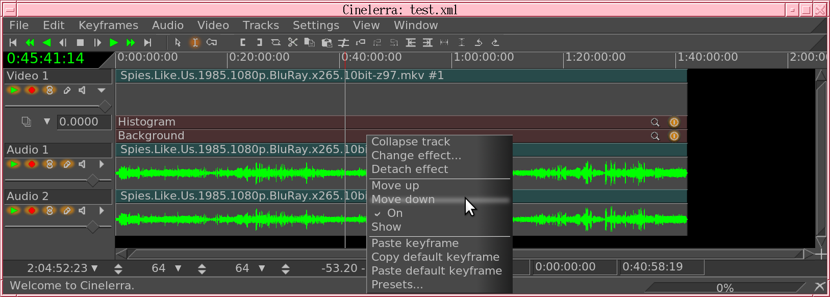
Change the project size to 512x512. Be sure the track size is big enough to contain the color cube. Change the projector to left top justify. Render 1 frame to a PNG image. The color cube must fill the entire 512x512 output & be aligned exactly.
There is no cookie cutter feature to generate a LUT because it’s an extremely rarely used feature.
Next: REFRAMERT, Previous: LUT, Up: EFFECTS NOTES [Contents]
| • BLOB TRACKER: | Stabilization using blob detection | |
| • MOTION: | Motion tracking with rotation. | |
| • MOTION 2 POINT: | Motion and rotation tracking from translation only. | |
| • SUPER STABILIZER: | Basic stabilization |
Next: MOTION, Up: MOTION EFFECTS [Contents]
This effect stabilizes video by centering on the left edge of a matching blob. Blob tracker is designed to be used with a chroma key or threshold effect. It’s most effective for stabilizing flying things or things which can be easily keyed.
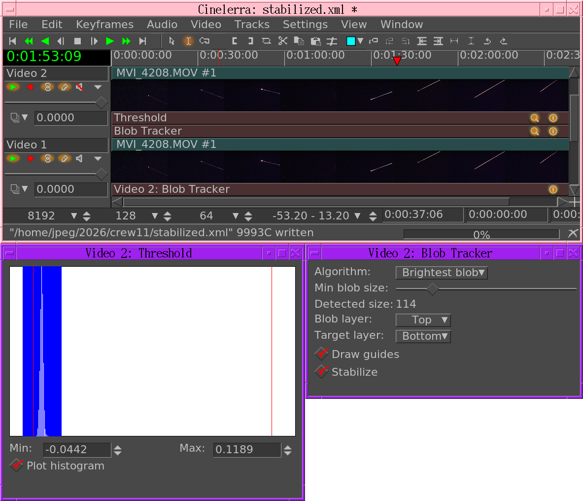
The chroma key or threshold sets matching areas to 0 alpha or black. If the color model has alpha, blob tracker takes the 0 alpha as blobs. If the color model has no alpha, blob tracker takes black areas as blobs. Threshold doesn’t zero out the alpha, so it has to be used with a 3 channel color model. It further selects 1 winner from all the blobs. It shifts the bottom track based on the blob detected in the top track.
The ALGORITHM option selects the type of blob. If it is Largest it goes for the largest blob. If it is Brightest it goes for the brightest blob of any size. The brightness value is always taken from the target layer. The blob outlines are always taken from the blob layer.
The minimum blob size it detects is determined by the Min blob size option. This is the square root of the total number of pixels in the blob. Detected size shows the square root of the largest blob size detected in the current frame, to aid in setting the limit.
Blob layer & Target layer determine what input is used for blob detection, brightness detection, & stabilization.
Draw guides draws the outline of the winning blob.
Stabilize shifts the target layer to center the winning blob.
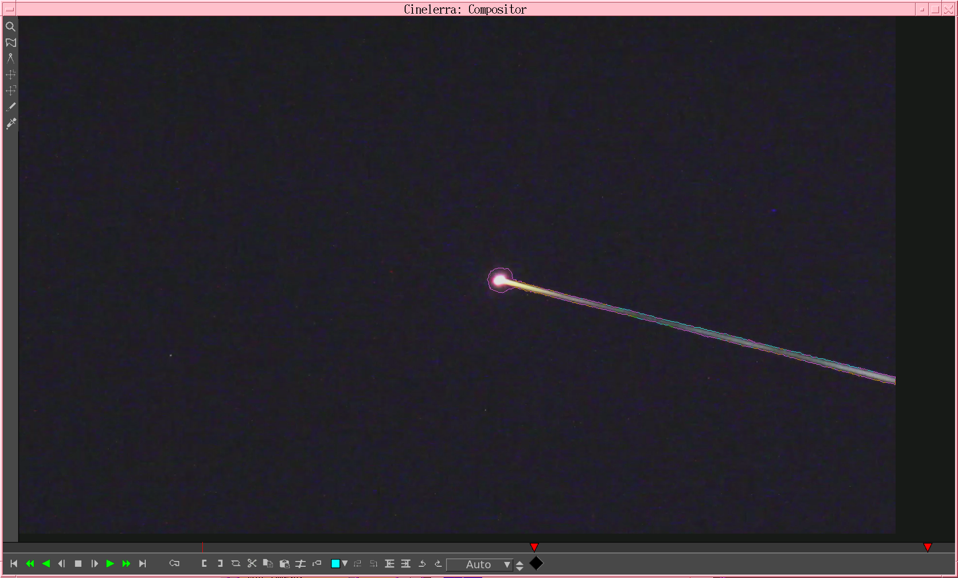
In this case, it has stabilized on the brightest blob, outlining it.
If the result is too shaky, make the keying more selective & reduce the minimum blob size to shrink the hit size.
Next: MOTION 2 POINT, Previous: BLOB TRACKER, Up: MOTION EFFECTS [Contents]
The motion tracker is almost a complete application in itself. The motion tracker tracks two types of motion: translation and rotation. It can track both simultaneously or one only. It can do 1/4 pixel tracking or single pixel tracking. It can stabilize motion or cause one track to follow the motion of another track.
Although the motion tracker is applied as a realtime effect, it usually must be rendered to see useful results. The effect takes a long time to precisely detect motion.
The motion tracker works by using one region of the frame as the region to track. It compares this region between 2 frames to calculate the motion. This region can be defined anywhere on the screen. Once the motion between 2 frames has been calculated, a number of things can be done with that motion vector. It can be scaled by a user value and clamped to a maximum range. It can be thrown away or accumulated with all the motion vectors leading up to the current position.
To save time the motion result can be saved for later reuse, recalled from a previous calculation, or discarded.
The motion tracker has a notion of 2 tracks, the master layer and the target layer. The master layer is where the comparison between 2 frames takes place. The target layer is where motion is applied either to track or compensate for the motion in the master layer.
The intricacies of motion tracking are enough to sustain entire companies and build careers around. The motion tracker in Cinelerra isn’t as sophisticated as some world class motion trackers but it’s enough to sweeten some camcorder footage.
Here is a brief description of the motion tracking parameters:
Translation options:
Rotation options:
Global options:
When rotation is enabled a single box the size of the rotation block is drawn rotated by the amount of rotation detected.
Next: 2 PASS MOTION TRACKING, Up: MOTION [Contents]
Since it is a very slow effect, there is a method to applying the motion tracker to get the most out of it. First disable playback for the track to do motion tracking on. Then drop the effect on a region of video with some motion to track. Then rewind the insertion point to the start of the region. Set Action -> Do Nothing. Set Calculation -> Don’t calculate. Enable Draw vectors. Then enable playback of the track to see the motion tracking areas.
Enable which of translation motion or rotation motion vectors you want to track. By watching the compositor window and adjusting the Block x,y settings, center the block on the part of the image you want to track. Then set search radius, block size, and block coordinates for translation and rotation.
Once this is configured, set the calculation to Save coords and do test runs through the sequence to see if the motion tracker works and to save the motion vectors. Once this is done, disable playback for the track, disable Draw vectors, set the motion action to perform on the target layer and change the calculation to Load coords. Finally enable playback for the track.
When using a single starting frame to calculate the motion of a sequence, the starting frame should be a single frame with the least motion to any of the other frames. This is rarely frame 0. Usually it’s a frame near the middle of the sequence. This way the search radius need only reach halfway to the full extent of the motion in the sequence.
If the motion tracker is used on a render farm, Save coords and previous frame mode won’t work. The results of the save coords operation are saved to the hard drives on the render nodes, not the master node. Future rendering operations on these nodes will process different frames and read the wrong coordinates from the node filesystems. The fact that render nodes only visualize a portion of the timeline also prevents previous frame from working since it depends on calculating an absolute motion vector starting on frame 0.
Next: USING BLUR TO IMPROVE MOTION TRACKING, Previous: SECRETS OF MOTION TRACKING, Up: MOTION [Contents]
The method described above is 2 pass motion tracking. One pass is used just to calculate the motion vectors. A second pass is used to apply the motion vectors to the footage. This is faster than a single pass because errors in the motion vector calculation can be discovered quickly.
This also allows the motion tracking to use a less demanding colormodel like RGB888 in the scanning step and a more demanding colormodel like RGB Float in the action step. The scanning step takes much longer than action.
This suffers the disadvantage of not being practical for extremely long sequences where some error is acceptable and the picture quality is lousy to begin with, like stabilizing camcorder footage.
The slower method is to calculate the motion vectors and apply them simultaneously. This method can use one track as the motion vector calculation track and another track as the target track for motion vector actions. This is useful for long sequences where some error is acceptable.
Next: USING HISTOGRAM TO IMPROVE MOTION TRACKING, Previous: 2 PASS MOTION TRACKING, Up: MOTION [Contents]
With extremely noisy or interlaced footage, applying a blur effect before the motion tracking can improve accuracy. Either save the motion vectors in a tracking pass and disable the blur for the action pass or apply the blur just to the master layer.
Next: INTERPOLATING MOTION BETWEEN FRAMES, Previous: USING BLUR TO IMPROVE MOTION TRACKING, Up: MOTION [Contents]
A histogram is almost always applied before motion tracking to clamp out noise in the darker pixels. Either save the motion vectors in a tracking pass and disable the histogram for the action pass or apply the histogram just to the master layer.
Next: FILLING IN THE BLACK AREAS, Previous: USING HISTOGRAM TO IMPROVE MOTION TRACKING, Up: MOTION [Contents]
The motion tracker can simulate higher frame rates than the media frame rate by interpolating the motion. Interpolation is enabled with the maximum absolute offset and settling speed options.
First, go to Settings->Format in the main window and set the video frame rate to a number higher than the media frame rate.
In the Motion window, select a tracking option which accumulates motion. This is either Track previous frame or Previous frame same block. These cause the maximum absolute offset and settling speed options to take effect.
maximum absolute offset must be set to the maximum motion to be accumulated as a percentage of the video size. A value of 50 limits the motion to 50% of the video size. 50 works well. The value must be smaller for larger translation block sizes so there is enough area under the block to sense motion with.
settling speed must be set to the rate at which the accumulated motion resets to 0 over time. The reset happens whether or not any motion was detected, so when the project frame rate is higher than the media frame rate, the frames between media frames regress towards the center. For interpolated motion, the settling speed value should be small, so the movement is smooth. 3 works well.
Previous: INTERPOLATING MOTION BETWEEN FRAMES, Up: MOTION [Contents]
Stabilization always creates black borders in the track resolution. One solution is to shrink the project resolution so the borders are always cropped off the output. Another solution is to apply a Time Average effect after stabilization.
Configure Time Average the following way:
This makes new frames replace only the pixels in the previous frames where there is new data. The black areas in new frames don’t replace previous data so the previous data shows through and fills them in.
Next: SUPER STABILIZER, Previous: MOTION, Up: MOTION EFFECTS [Contents]
The 2 point motion tracker is the same as using 2 of the translation motion trackers to track 2 points. It doesn’t have a rotation tracker. Instead, it uses the angle between the 2 translation points to determine rotation. The 2 points can be enabled separately.
If 1 point is enabled, only translation is tracked.
If 2 points are enabled, translation is tracked by point 1 and rotation is tracked by point 2. Stabilization is performed with point 1 as the center.
The other parameters for the 2 point tracker are the same as the single point tracker. In addition, the 2 point tracker supports TRANSLATION SEARCH OFFSET.
TRANSLATION SEARCH OFFSET forces the motion search to look in a region other than directly next to the translation block position. The translation search offset is added to the new search result, giving contiguous motion results throughout any changes in translation search area.
This is useful if the camera position changed in the middle of a sequence of images but the subject stayed the same. Offset the translation search area when the camera position changes and the detected motion stays contiguous through the entire sequence.
2 point tracking works best if the points don’t change shape between frames. It is more prone to rotation errors than single point motion tracking if the points change shape. 2 point tracking is mainly used for tracking stars.
Use the smallest search blocks possible since larger blocks are harder to compare when they’re rotated.
Previous: MOTION 2 POINT, Up: MOTION EFFECTS [Contents]
New techniques specifically for stabilizing video emerged. The previous motion effects were quite large so a new effect was created just for stabilizing video. It’s not intended to be accurate as much as make footage look good.
The key step it does is read ahead by a certain number of frames to determine the future drift of the motion estimation. Then it interpolates every frame to take out the future drift. This has proven superior to centering on past accumulated motion over time. It hides oscillating motion. If it knows a future motion is going to be the opposite of a past motion, it can avoid centering on the past motion.
The main drawback with super stabilizer is it’s super slow. To use it, disable the play toggle for the track, then attach it. Disable Enable in the super stabilizer. Then enable the play toggle for the track. Enable Draw vectors to configure the super stabilizer. Once configured, enable Enable & wait for the lookahead buffer to fill.
Super stabilizer uses a single search block & only detects motion after the previous frame. There is no maximum setting for the accumulated drift because the lookahead buffer will always keep it from drifting no farther than where it is in the future. Because the accumulated drift heads toward infinity, it’s not practical to have a maximum accumulated drift.
Like the other motion effects, best results depend on the search block having enough details & not having repeating patterns.
Enable Enables processing for the super stabilizer. Does not affect the drawing of the vectors. Disable it to configure the effect.
Number of frames to look ahead the size of the lookahead buffer. All these frames are stored in RAM. The longer it is, the more stable the footage but the longer it takes to get started until it’s unusable.
Translation search radius How far to search around the search block.
Translation block size How big the search block is.
Block position Where the search area is.
Track rotation Rotation tracking is optional
Maximum angle offset How far to search for the rotation.
Draw vectors Draws the search block to allow configuration.
Next: REFRAME, Previous: MOTION EFFECTS, Up: EFFECTS NOTES [Contents]
ReframeRT changes number of frames in a sequence of video directly from the timeline. It has 2 modes, selected by the 2 toggles in the GUI.
Stretch mode multiplies the current frame number of its output by the scale factor to arrive at the frame to read from its input. If its current output frame is #55 and the scale factor is 2, frame #110 is read from its input. The stretch mode has the effect of changing the length of output video by the inverse of the scale factor. If the scale factor is greater than 1, the output will end before the end of the sequence on the timeline. If it’s less than 1, the output will end after the end of the sequence on the timeline. The ReframeRT effect must be lengthened to the necessary length to accommodate the scale factor. Change the length of the effect by clicking on the endpoint of the effect and dragging.
Although stretch mode changes the number of the frame read from its input, it doesn’t change the frame rate of the input. Effects before ReframeRT assume the same frame rate as ReframeRT.
Downsample mode doesn’t change the length of the output sequence. It multiplies the frame rate of the output by the scale factor to arrive at a frame rate rate to read the input. This has the effect of replicating the input frames so that they only change at the scaled frame rate when sent to the output. It doesn’t change the length of the sequence. If the scale factor is 0.5 and the output frame rate is 30 fps, only 15 frames will be shown per second and the input will be read at 15 fps. Downsample is only useful for scalefactors below 1, hence the name downsample.
Downsample mode changes the frame rate of the input as well as the number of the frame to read, so effects before ReframeRT see the frame rate * the scale factor as their frame rate. If the scale factor is 2 and the output frame rate is 30, the input frame rate will be 60 and the input frame number will by doubled. This won’t normally do anything but some input effects may behave differently at the higher frame rate.
Next: RESAMPLE, Previous: REFRAMERT, Up: EFFECTS NOTES [Contents]
This does exactly the same thing as ReframeRT in Stretch mode. It multiplies the output frame number by the scale factor to arrive at the input frame number and changes the length of the sequence. Unlike ReframeRT, this must run from the Video menu and render its output.
Be aware Reframe doesn’t write the scaled frame rate as the frame rate of the rendered file. It produces a file of scaled length and equal frame rate as the project. The new length is 1/scale factor as big as the original sequence.
Next: REVERSE VIDEO/AUDIO, Previous: REFRAME, Up: EFFECTS NOTES [Contents]
This multiplies the number of each output sample by a scale factor to arrive at the number of the input sample. The output file’s sample rate is set to the project sample rate but its length is changed to reflect the scaled number of samples. It also filters the resampled audio to remove aliasing.
If the scale factor is 2, every 2 input samples will be reduced to 1 output sample and the output file will have half as many samples as the input sequence. If it’s 0.5, every 0.5 input samples will be stretched to 1 output sample and the output file will have twice as many samples as the input sequence.
Next: SWAP FRAMES, Previous: RESAMPLE, Up: EFFECTS NOTES [Contents]
Media can be reversed on the timeline in realtime. This isn’t to be confused with using the reverse playback on the transport. The reverse effects reverse the region covered by the effect regardless of the transport direction. Apply reverse audio to an audio track and play it backwards. The sound plays forward.
The region to be reversed is first determined by what part of the track the effect is under and second by the locations of keyframes in the effect. The reverse effects have an enabled option which allows you to set keyframes. This allows may possibilities.
Every enabled keyframe is treated as the start of a new reversed region and the end of a previous reversed region. Several enabled keyframes in succession yield several regions reversed independent of each other. An enabled keyframe followed by a disabled keyframe yields one reversed region followed by a forward region.
Finally, be aware when reversing audio that the waveform on the timeline doesn’t reflect the actual reversed output.
Next: SWAP CHANNELS, Previous: REVERSE VIDEO/AUDIO, Up: EFFECTS NOTES [Contents]
This is normally used on interlaced video which has been converted to fields. One set of lines becomes one frame and the other set of lines becomes the next frame. Now the frame rate is double and is showing fields of the original video sequentially. The fields may be out of order, which is what SWAP FRAMES can correct.
Next: THRESHOLD, Previous: SWAP FRAMES, Up: EFFECTS NOTES [Contents]
In RGB colorspaces, this sends the user specified R, G, B channel in the source channel column to the destination channel in the destination column. In YUV colorspaces, the RGB selection corresponds to Y, U, V channels. The alpha is always a discrete channel but not present unless the project has an alpha.
If swap channels is shared between multiple tracks, the source track is selected by the source buffer. Source buffer 0 is the top track. Higher numbered source buffers are the lower tracks in the timeline.
The same output is copied to all the shared tracks so some projects can perform different processing on each output track. The alpha in 2 overlapping tracks will accumulate, so you must mute the lower tracks to avoid this.
Next: TIME AVERAGE, Previous: SWAP CHANNELS, Up: EFFECTS NOTES [Contents]
Threshold converts the image to pure luminance. Then luminance values below and above the threshold range are converted to black and luminance values inside the threshold range are converted to white. The threshold window shows a histogram of luminance values for the current frame. Click dragging inside the histogram creates a range to convert to white. Shift-clicking extends one border of this range. Values for the threshold range can also be specified in the text boxes.
This effect is basically a primitive luminance key. A second track above the track with the threshold effect can be multiplied, resulting in only the parts of the second track within the threshold being displayed.
Next: TIME FRONT, Previous: THRESHOLD, Up: EFFECTS NOTES [Contents]
Time average is one effect which has many uses besides creating nifty trail patterns of moving objects. It’s main use is reducing noise in still images. Merely point a video camera at a stationary subject for 30 frames, capture the frames, and average them using TIME AVERAGE and you’ll have a super high quality print. In floating point colormodels, time average can increase the dynamic range of lousy cameras.
Inside the time average effect is an accumulation buffer and a divisor. A number of frames are accumulated in the accumulation buffer and divided by the divisor to get the average.
Because the time average can consume enormous amounts of memory, it is best applied by first disabling playback for the track, dropping the time average in it, configuring time average for the desired number of frames, and re-enabling playback for the track.
Frames count: This determines the number of frames to be accumulated in the accumulation buffer. For extremely large integrations it’s easier to edit the EDL in a text editor and put in the number of frames.
Accumulate sequence again: If an effect before the time average is adjusted the time average normally doesn’t reread the accumulation buffer to get the change. This forces it to reread the accumulation buffer when any other effects change.
Average: This causes the accumulation buffer to be divided before being output. The result is the average of all the frames.
Accumulate: This outputs the accumulation buffer without dividing it. The result is the sum of all the frames.
Accumulate only:
In order to accumulate only the specified number of frames, the time average retains all the previous frames in memory and subtracts them out as it plays forward. Accumulate only: causes the history buffer to not be used in averaging and accumulating. Without the history buffer, frames are added endlessly without ever being subtracted. It’s the same as an infinitely long accumulation buffer. The only difference is for Average mode, the output is still divided by the Frame count. Accumulate only is used where the number of frames in the accumulation would be too big to fit in memory.
Replace: This causes the accumulation buffer to be replaced by only pixels which aren’t transparent. This allows black borders from motion tracking to be filled in.
Threshold: The value a pixel must be before it replaces the previous pixel. If alpha channels are enabled, the alpha is the value compared. If there is no alpha channel, the brightness is the value compared.
Border: The number of pixels on the border of the image to never replace. This hides errors in the replacement operation from the output, since errors occur at the transition between the replaced area and the ignored area.
Greater: Pixels are replaced if their value is greater than the previous pixel. Use this to create star trails in stacks of many night sky photos or paint many copies of an object from its motion if it is lighter than the background.
Less: Pixels are replaced if their value is less than the previous pixel. Use this to paint copies of an object from its motion if it is darker than the background.
Next: TITLER, Previous: TIME AVERAGE, Up: EFFECTS NOTES [Contents]
This takes each pixel from different frames in a history buffer. The selection of what frame in the history goes to each pixel is determined by the pixel’s alpha value in an alpha mask. The alpha mask can be generated synthetically or be taken from a video source.
The history buffer always starts from the lower numbered frames in the timeline & goes to the current frame - 1, regardless of the playback direction. If the mask pixel is 0, the lowest numbered frame is taken. If the mask pixel is maximum, the highest numbered frame is taken.
Type: The source of the mask. Linear, Radial: generate synthetic gradients. These have extra options to define the gradient. Alpha as timefront: uses the alpha in the current frame. Other track: uses either the luminance or the alpha of another track.
Angle, rate, inner radius, outer radius: Define the shape if a synthetic gradient is used.
Time range: Number of frames in the history buffer. These are in addition to the current frame, so 1 rewinds 1 frame. 255 rewinds 255 frames.
Inversion: Reverses the history buffer so the most recent frame is taken for mask values of 0 & the oldest frame is taken for mask values of maximum.
Show grayscale for tuning: Shows the mask instead of the output frame. The level of grayscale is a visual indicator of what frame is taken from the history buffer for each pixel.
Next: VIDEO SCOPE, Previous: TIME FRONT, Up: EFFECTS NOTES [Contents]
While it is possible to add text to movies by importing still images from The Gimp and compositing them, the Titler allows you to add text from within Cinelerra.
The titler has standard options for font, size, and style. The best font is a generic, normal font like Arial in a large size.
The titler also has options you’ll only find in moving pictures. The Justify operation justifies the text relative to the entire frame. Once justified, the X and Y offset is applied. This allows text to be justified while at the same time letting you push it within the title safe region.
The motion type scrolls the text in any of the four directions. When using this, the text may disappear. Move the insertion point along the timeline until the text is far enough along the animation to reappear. The text scrolls on and scrolls off.
Setting loop causes the text to scroll completely off and repeat. Without loop the text scrolls off and never reappears.
The speed of the animation is determined by speed Set it higher to speed up the animation.
DROP SHADOW draws a black copy of the text to the bottom right of the original text. Useful when drawing text over changing video to keep the border always visible.
In addition to the scrolling, Fade in/Fade out are a second type of animation. If the fade seconds are 0, no fading is done.
OUTLINE draws an outline on the characters if it’s greater than 0. Set the outline size by changing the number. Set the outline color with the OUTLINE COLOR button. If no outline is visible, make sure the alpha in OUTLINE COLOR is nonzero. To get pure outline characters, set COLOR alpha to 0.
COLOR picks the color to draw the text in. Usually white is the only practical color.
OUTLINE COLOR picks the color to draw the text outline in.
STAMP TIMECODE replaces the text with the current position on the timeline in seconds and frames.
USE SUBTITLE FILE causes it to read the text from a .srt subtitle file. Because subtitles normally don’t show long enough, it has a hack which causes it to not hide the subtitle until the next one is due.
Because they don’t time out, it’s best to draw the subtitles below the video instead of on top of it.
SECRETS OF THE TITLER
| • ADDING FONTS TO THE TITLER: | How to add fonts to the titler | |
| • MAKING TITLES LOOK GOOD: | How to make your titles look good. |
Next: MAKING TITLES LOOK GOOD, Up: TITLER [Contents]
Cinelerra uses libfreetype for drawing titles. It has a few limitations: it can’t automatically use the fonts installed in the X server. It can’t automatically determine the files to use for normal, italic, bold. Some distributions began putting all their fonts in /usr/share/fonts but different programs still have their own directories to guarantee they work.
The easiest way to support fonts has been to put the .ttf files in cinelerra/fonts. Then run ttmkfdir > fonts.dir and restart Cinelerra. The new fonts should appear. The usage of ttmkfdir changes frequently so this technique might not work.
The titler supports whatever ttmkfdir & freetype support, mainly TTF, true type fonts. Other font formats like OTF are best converted to TTF. It’s not the biggest limitation of the titler.
Previous: ADDING FONTS TO THE TITLER, Up: TITLER [Contents]
No-one else is going to tell you this, but to make good looking titles, ignore most of the features of the titler. The best settings are:
Don’t waste the audience’s time with fading & crawls. Use crawls only if there’s too much text to fit on the screen. The title should be legible enough to take the least amount of time to read. You’re supposed to show the story, not write it. If they wanted to read a story, they would be reading a book instead of watching video.
Previous: TITLER, Up: EFFECTS NOTES [Contents]
The video scope plots two views of the image. One view plots the intensity of each pixel against horizontal position. They call this the WAVEFORM. Another view translates hue to angle and saturation to radius for each pixel. They call this the VECTORSCOPE.
The vectorscope is actually very useful for determining if an image is saturated. When adjusting saturation, it’s important to watch the vectorscope to make sure pixels don’t extend past the 100 radius.
The waveform allows you to make sure image data extends from complete black to complete white while adjusting the brightness/contrast.
Some thought is being given to having a video scope for recording. Unfortunately, this would require a lot of variations of the video scope for all the different video drivers.
Next: KEYBOARD SHORTCUTS, Previous: EFFECTS NOTES, Up: TOP [Contents]
The plugin API in Cinelerra dates back to 1997, before the LADSPA and before VST became popular. The main features are support for showing realtime graphics during playback, random access from plugins, keyframes, realtime adjustment during playback. 1 unique thing is the GUI is not abstracted from the programmer. The windows, window sizes & graphics are all customizable but it’s more labor intensive.
There are several types of plugins. The easiest way to implement a plugin is to take the simplest existing one out of the group and extend it.
The key types of plugins are audio, video, transitions, non realtime, realtime, multi channel, single channel. Some possible types have never been created because no practical need was found. There are very few non realtime plugins still around, since new features like random access have made that mode unnecessary. Non realtime mode is generally for very slow effects which need random access. Transitions only support single channel.
Simple examples of each plugin type are given in the table.
| • THE PULL METHOD: | How random access reads work | |
| • COMMON PLUGIN OBJECTS: | What all effects have to do. | |
| • REALTIME PLUGINS: | What realtime effects have to do. | |
| • NONREALTIME PLUGINS: | What rendered effects have to do. | |
| • AUDIO PLUGINS: | What audio effects have to do. | |
| • VIDEO PLUGINS: | What video effects have to do. | |
| • TRANSITION PLUGINS: | What transitions have to do. | |
| • PLUGIN GUI'S WHICH UPDATE DURING PLAYBACK: | How to draw currently playing data in the GUI. | |
| • PLUGIN QUERIES: | How plugins get information about the data to be processed. | |
| • USING OPENGL: | How to use hardware to speed up operations. |
Next: COMMON PLUGIN OBJECTS, Up: PLUGIN AUTHORING [Contents]
Originally plugins were designed with the push method. The push method is intuitive and simple. A source pushes data to a plugin, the plugin does math operations on it, and the plugin pushes it to a destination. For 6 years this was the way all realtime plugins were driven internally but it didn’t allow you to reduce the rate of playback in realtime. While plugins can still be designed as if they’re pushing data, this is not the way they’re processed internally anymore.
The latest evolution in Cinelerra’s plugin design is the pull method. The rendering pipeline starts at the final output and the final step reads from the previous step in the rendering pipeline. Every step in the rendering chain involves reading from the previous step. Each step can request data from a different point in time so the plugins have random access, can change sample rates.
Plugins have access to the project rates get_project_samplerate() get_project_framerate(), or the requested rate the next step in rendering is running at get_samplerate() get_framerate(). The project rates are used for reading keyframes. The rendering rate is what the start position & source data is in.
Keyframes for a plugin are stored relative to the project frame rate. Queries from a plugin for the current playback position are given relative to the project frame rate. If the plugin’s output was requested to be at twice the project frame rate, the positions need to be converted to the project rate for keyframes to match up. Two classes of data rates were created to handle this problem.
Rate conversions are done in terms of the project rate and the requested rate. The project rate is identical for all plugins. It is determined by the settings->format window. The requested rate is determined by the downstream plugin requesting data from the current plugin. The requested rate is arbitrary. Exactly how to use these rates is described below.
Next: REALTIME PLUGINS, Previous: THE PULL METHOD, Up: PLUGIN AUTHORING [Contents]
All plugins inherit from a derivative of PluginClient. This PluginClient derivative implements most of the required methods in PluginClient, but users must still define methods for PluginClient. The most commonly used methods are predefined in macros to reduce the typing yet still allow flexibility.
The files they include depend on the plugin type. Audio plugins include pluginaclient.h and video plugins include pluginvclient.h. They inherit PluginAClient and PluginVClient respectively.
Cinelerra instantiates all plugins at least twice when they are used in a movie. One instance is the GUI. The other instance is the rendering processor. User input, through a complicated sequence, is propagated from the GUI instance to the rendering instance. If the renderer wants to alter the GUI, it propagates data back to the GUI instance.
All plugins define at least three objects:
The window has pointers to a number of widgets, a few initialization methods, and a back pointer to the plugin’s processing object. The GUI uses Cinelerra’s toolkit. The plugin abstraction layer handles creating a thread for the GUI.
| • THE PROCESSING OBJECT: | ||
| • THE CONFIGURATION OBJECT: | ||
| • THE USER INTERFACE OBJECT: |
Next: THE CONFIGURATION OBJECT, Up: COMMON PLUGIN OBJECTS [Contents]
The processing objects have a lot of predefined functions defined in macros like
PLUGIN_CLASS_MEMBERS2(config_name, thread_name)
REGISTER_PLUGIN
NEW_WINDOW_MACRO
LOAD_CONFIGURATION_MACRO
The commonly used members in PLUGIN_CLASS_MEMBERS2 are described below.
The macros apply mainly to realtime plugins and are not useful in nonrealtime plugins. Fortunately, nonrealtime plugins are simpler.
You have to define a bunch of functions to describe the capabilities of the plugin.
should return 1 if one instance of the plugin handles multiple tracks simultaneously or 0 if one instance of the plugin only handles one track. The default is 0 if it is omitted.
Multichannel plugins in their processing function should refer to a function called PluginClient::get_total_buffers() to determine the number of channels.
Tells if the plugin is realtine or not.
Loads the configuration based on surrounding keyframes and current position. This one is normally defined by a macro.
LOAD_CONFIGURATION_MACRO(plugin_class, config_class)
to implement the default behavior for load_configuration. This stores whatever the current configuration is inside the plugin’s configuration object and returns 1 if the new configuration differs from the previous configuration. The return value of load_configuration is used by another commonly used function, update_gui to determine if the GUI really needs to be updated.
The plugin’s configuration object is always called config inside PLUGIN_CLASS_MEMBERS2.
Returns a text string identifying the plugin in the resource window. The string has to be unique.
This is called during playback & scrubbing to update the parameters in the GUI.
It should first load the configuration, test for a return of 1, and then redraw the GUI if the parameters changed. All the plugins using GuiCast have a format like
void MyPlugin::update_gui()
{
	if(thread)
	{
		if(load_configuration())
		{
			thread->window->lock_window();
// update widgets here
			thread->window->unlock_window();
		}
	}
}
to handle concurrency and conditions of no GUI.
Important functions the processing object must define are the functions which load and save configuration data from keyframes. These functions are called by the macros so all you need to worry about is accessing the keyframe data.
The *data functions are only used in realtime plugins. They access the default settings as well as the keyframe data. If they’re being called to access default settings is_defaults() returns 1. This way the defaults can contain different parameters than the keyframes.
The *data functions translate the plugin configuration between the KeyFrame argument and the configuration object for the plugin. The keyframes are stored on the timeline and can change for every project.
Inside the keyframe is an ordinary string. It’s most easily parsed by creating a FileXML object. That has XML translation and some specific commands to get the data out of the KeyFrame argument. See any existing plugin to see the usage of KeyFrame and FileXML.
The *defaults functions are only used in non realtime plugins to get their settings. The defaults functions translate the plugin configuration between a BC_Hash object and the plugin’s configuration. The BC_Hash object stores configurations in a discrete file on disk for each plugin but doesn’t isolate different configurations for different projects.
The function overriding load_defaults also needs to call defaults = new BC_Hash(path); with the configuration path. See any existing plugin to see the usage of BC_Hash. The function overriding save_defaults does not create defaults.
Other standard members may be defined in the processing object, depending on the plugin type.
Next: THE USER INTERFACE OBJECT, Previous: THE PROCESSING OBJECT, Up: COMMON PLUGIN OBJECTS [Contents]
The configuration object is critical for GUI updates, signal processing, and default settings in realtime plugins. Be aware it is not used in nonrealtime plugins. The configuration object inherits from nothing and has no dependencies. It’s merely a class containing three functions and variables specific to the plugin’s parameters.
Usually the configuration object starts with the name of the plugin followed by Config.
class MyPluginConfig
{
public:
	MyPluginConfig();
Following the name of the configuration class, we put in three required functions and the configuration variables.
	int equivalent(MyPluginConfig &that);
	void copy_from(MyPluginConfig &that);
	void interpolate(MyPluginConfig &prev,
		MyPluginConfig &next,
		int64_t prev_position,
		int64_t next_position,
		int64_t current_position);


	float parameter1;
	float parameter2;
	int parameter3;
};
Now you must define the three functions. Equivalent is called by LOAD_CONFIGURATION_MACRO to determine if the local configuration parameters are identical to the configuration parameters in the argument. If equivalent returns 0, the LOAD_CONFIGURATION_MACRO causes the GUI to redraw. If equivalent returns 1, the LOAD_CONFIGURATION_MACRO doesn’t redraw the GUI.
Then there’s copy_from which transfers the configuration values from the argument to the local variables. This is once again used in LOAD_CONFIGURATION_MACRO to store configurations in temporaries. Once LOAD_CONFIGURATION_MACRO has replicated the configuration, it loads a second configuration. Then it interpolates the two configurations to get the current configuration. The interpolation function performs the interpolation and stores the result in the local variables.
Normally the interpolate function calculates a previous and next fraction, using the arguments.
void MyPluginConfig::interpolate(MyPluginConfig &prev,
		MyPluginConfig &next,
		int64_t prev_position,
		int64_t next_position,
		int64_t current_position)
{
	double next_scale = (double)(current_position - prev_position) / (next_position - prev_position);
	double prev_scale = (double)(next_position - current_position) / (next_position - prev_position);
Then the fractions are applied to the previous and next configuration variables to yield the current values.
	this->parameter1 = (float)(prev.parameter1 * prev_scale + next.parameter1 * next_scale);
	this->parameter2 = (float)(prev.parameter2 * prev_scale + next.parameter2 * next_scale);
	this->parameter3 = (int)(prev.parameter3 * prev_scale + next.parameter3 * next_scale);
}
Alternatively you can copy the values from the previous configuration argument if no interpolation is desired.
This usage of the configuration object is the same in audio and video plugins. In video playback, the interpolation function is called for every frame, yielding smooth interpolation. In audio playback, the interpolation function is called only once for every console fragment and once every time the insertion point moves. This is good enough for updating the GUI while selecting regions on the timeline but it may not be accurate enough for really smooth rendering of the effect.
For really smooth rendering of audio, you can still use load_configuration when updating the GUI. For process_buffer; however, ignore load_configuration and write your own interpolation routine which loads all the keyframes in a console fragment and interpolates every sample. This would be really slow and hard to debug, yielding improvement which may not be audible. Then of course, every country has its own wierdos.
An easier way to get smoother interpolation is to reduce the console fragment to 1 sample. This would have to be rendered and played back with the console fragment back over 2048 of course. The Linux sound drivers can’t play fragments of 1 sample.
Previous: THE CONFIGURATION OBJECT, Up: COMMON PLUGIN OBJECTS [Contents]
The user interface object is derived from PluginClientWindow. The user must call NEW_WINDOW_MACRO in the processing object to create the PluginClientWindow. This system is used in realtime plugins but not in nonrealtime plugins.
Nonrealtime plugins create and destroy their own GUI in their get_parameters function and there’s no need for a PluginClientWindow subclass.
Now the window class must be declared in the plugin header. It’s easiest to implement the window by copying an existing plugin and renaming the symbols. The following is an outline of what happens. The plugin header must declare the window’s constructor using the appropriate arguments.
#include "guicast.h"

MyWindow::MyWindow(MyPlugin *plugin)
 : PluginClientWindow(plugin,
	440,
	500,
	440,
	500,
	0)
{
This becomes a window on the screen with the size given by the arguments to PluginClientWindow.
It needs two methods
void create_objects();
and a back pointer to the plugin
MyPlugin *plugin;
The create_objects member puts widgets in the window according to GuiCast’s syntax. A pointer to each widget which you want to synchronize to a configuration parameter is stored in the window class. These are updated in the update_gui function you earlier defined for the plugin. The widgets are usually derivatives of a GuiCast widget and they override functions in GuiCast to handle events. Finally create_objects calls
show_window();
to make the window appear all at once.
Every widget in the GUI needs to detect when its value changes. In GuiCast the handle_event method is called whenever the value changes. In handle_event, the widget then needs to call plugin->send_configure_change() to propagate the change to any copies of the plugin which are processing data.
Next: NONREALTIME PLUGINS, Previous: COMMON PLUGIN OBJECTS, Up: PLUGIN AUTHORING [Contents]
Realtime plugins should use PLUGIN_CLASS_MEMBERS to define the basic set of members in their headers. All realtime plugins must define an
int is_realtime()
member returning 1. This causes a number of methods to be called during live playback and the plugin to be usable on the timeline.
Realtime plugins must override a member called
process_buffer
This function takes different arguments depending on if the plugin handles video or audio. See an existing plugin to find out which usage applies.
The main features of the process_buffer function are a buffer to store the output, the starting position of the output, and the requested output rate. For audio, there’s also a size argument for the number of samples.
The starting position of the output buffer is the lowest numbered sample on the timeline if playback is forward and the highest numbered sample on the timeline if playback is reverse. The direction of playback is determined by one of the plugin queries described below.
The position and size arguments are all relative to the frame rate and sample rate passed to process_buffer. This is the requested data rate and may not be the same as the project data rate.
The process_realtime function should start by calling load_configuration. The LOAD_CONFIGURATION_MACRO returns 1 if the configuration changed.
After determining the plugin’s configuration, input media has to be loaded for processing. Call
read_frame(VFrame *buffer,
		int channel,
		int64_t start_position,
		double frame_rate)
or
read_samples(double *buffer,
		int channel,
		int sample_rate,
		int64_t start_position,
		int64_t len)
to request input data from the object which comes before this plugin. The read function needs a buffer to store the input data in. This can either be a temporary you create in the plugin or the output buffer supplied to process_buffer if you don’t need a temporary.
It also needs a set of position arguments to determine when you want to read the data from. The start position, rate, and len passed to a read function need not be the same as the values received by the process_buffer function. This way plugins can read data at a different rate than they output data.
The channel argument is only meaningful if this is a multichannel plugin. They need to read data for each track in the get_total_buffers() value and process all the tracks. Single channel plugins should pass 0 for channel.
Additional members are implemented to maintain configuration in realtime plugins. Some of these are also needed in nonrealtime plugins.
Next: AUDIO PLUGINS, Previous: REALTIME PLUGINS, Up: PLUGIN AUTHORING [Contents]
Some references for non-realtime plugins are Normalize for audio and Reframe for video.
To get settings, load_defaults and save_defaults must be implemented. These are not just used for default parameters but to transfer values from the user interface to the signal processor. There doesn’t need to be a configuration class in nonrealtime plugins.
Unlike realtime plugins, the LOAD_CONFIGURATION_MACRO can’t be used in the plugin header. Instead, the following methods must be defined.
The nonrealtime plugin should contain a pointer to a defaults object.
BC_Hash *defaults;
It should also have a pointer to a MainProgressBar.
MainProgressBar *progress;
The progress pointer allows nonrealtime plugins to display their progress in Cinelerra’s main window.
The constructor for a nonrealtime plugin can’t use PLUGIN_CONSTRUCTOR_MACRO but must call load_defaults directly.
The destructor, likewise, must call save_defaults and delete defaults directly instead of PLUGIN_DESTRUCTOR_MACRO.
char* plugin_title();
The usage of these is the same as realtime plugins.
This function must return 0 to indicate a nonrealtime plugin.
Here, the user should create a GUI, wait for the user to hit an OK button or a cancel button, and store the parameters in plugin variables. This routine must return 0 for success and 1 for failure. This way the user can cancel the effect from the GUI.
Unlike the realtime plugin, this GUI need not run asynchronously of the plugin. It should block the get_parameters function until the user selects OK or Cancel.
This should set the defaults variable to a new Defaults object and load parameters from the defaults object into plugin variables.
This should save plugin variables to the defaults object. It should not create the defaults object.
If get_parameters returned 0 for success, this is called once to give the plugin a chance to initialize processing. The plugin should instantiate the progress object with a line like
progress = start_progress("MyPlugin progress...",
	PluginClient::get_total_len());
The usage of start_progress depends on whether the plugin is multichannel or single channel. If it’s multichannel you always call start_progress. If it’s single channel, you first need to know whether the progress bar has already started in another instance of the plugin.
If PluginClient::interactive is 1, you need to start the progress bar. If it’s 0, the progress bar has already been started.
The PluginClient defines get_total_len() and get_source_start() to describe the timeline range to be processed. The units are either samples or frames and in the project rate.
This is called repeatedly until the timeline range is processed. It has either a samples or frames buffer for output and a reference to write_length to store the number of samples processed. If this is an audio plugin, the user needs to call get_buffer_size() to know how many samples the output buffer can hold.
The plugin must use read_samples or read_frame to read the input. These functions are a bit different for a non realtime plugin than they are for a realtime plugin.
They take a buffer and a position relative to the start of the timeline, in the timeline’s rate. Then you must process it and put the output in the buffer argument to process_loop. write_length should contain the number of samples generated if it’s audio.
Finally, process_loop must test PluginClient::interactive and update the progress bar if it’s 1.
progress->update(total_written);
returns 1 or 0 if the progress bar was cancelled. If it’s 1, process_loop should return 1 to indicate a cancellation. In addition to progress bar cancellation, process_loop should return 1 when the entire timeline range is processed.
This is called after process_loop processes its last buffer.
If PluginClient::is_interactive is 1, this should call stop_progress in the progress bar pointer and delete the pointer. Then it should delete any objects it created for processing in start_loop.
Next: VIDEO PLUGINS, Previous: NONREALTIME PLUGINS, Up: PLUGIN AUTHORING [Contents]
The simplest audio plugin is Gain. The processing object should include pluginaclient.h and inherit from PluginAClient. Realtime audio plugins need to define
int process_buffer(int64_t size,
		double **buffer,
		int64_t start_position,
		int sample_rate);
if it’s multichannel or
int process_buffer(int64_t size,
		double *buffer,
		int64_t start_position,
		int sample_rate);
if it’s single channel. These should return 0 on success and 1 on failure. In the future, the return value may abort failed rendering.
The processing function needs to request input samples with
int read_samples(double *buffer,
		int channel,
		int sample_rate,
		int64_t start_position,
		int64_t len);
It always returns 0. The user may specify any desired sample rate and start position.
Nonrealtime audio plugins need to define
int process_loop(double *buffer, int64_t &write_length);
for single channel or
int process_loop(double **buffers, int64_t &write_length);
for multi channel. Non realtime plugins use a different set of read_samples functions to request input data. These are fixed to the project sample rate.
Next: TRANSITION PLUGINS, Previous: AUDIO PLUGINS, Up: PLUGIN AUTHORING [Contents]
The simplest video plugin is Flip. The processing object should include pluginvclient.h and inherit from PluginVClient. Realtime video plugins need to define
int process_buffer(VFrame **frame,
	int64_t start_position,
	double frame_rate);
if it’s multichannel or
int process_buffer(VFrame *frame,
	int64_t start_position,
	double frame_rate);
if it’s single channel.
The nonrealtime video plugins need to define
int process_loop(VFrame *buffer);
for single channel or
int process_loop(VFrame **buffers);
for multi channel. The amount of frames generated in a single process_loop is always assumed to be 1, hence the lack of a write_length argument. Returning 0 causes the rendering to continue. Returning 1 causes the rendering to abort.
A set of read_frame functions exist for requesting input frames in non-realtime video plugins. These are fixed to the project frame rate.
Next: PLUGIN GUI'S WHICH UPDATE DURING PLAYBACK, Previous: VIDEO PLUGINS, Up: PLUGIN AUTHORING [Contents]
The simplest video transition is dissolve and the simplest audio transition is crossfade. These use a subset of the default class members of realtime plugins, but so far no analogue to PLUGIN_CLASS_MEMBERS has been done for transitions.
The processing object for audio transitions still inherits from PluginAClient and for video transitions it still inherits from PluginVClient.
Transitions may or may not have a GUI. If they have a GUI, they must also manage a thread like realtime plugins. Do this with the same PLUGIN_THREAD_OBJECT and PLUGIN_THREAD_HEADER macros as realtime plugins. Since there is only one keyframe in a transition, you don’t need to worry about updating the GUI from the processing object like you do in a realtime plugin.
If the transition has a GUI, you can use PLUGIN_CONSTRUCTOR_MACRO and PLUGIN_DESTRUCTOR_MACRO to initialize the processing object. You’ll also need a BC_Hash object and a Thread object for these macros.
Since the GUI is optional, overwrite a function called uses_gui() to signify whether or not the transition has a GUI. Return 1 if it does and 0 if it doesn’t.
Transitions need a load_defaults and save_defaults function so the first time they’re dropped on the timeline they’ll have useful settings.
A read_data and save_data function takes over after insertion to access data specific to each instance of the transition.
The most important difference between transitions and realtime plugins is the addition of an is_transition method to the processing object. is_transition should return 1 to signify the plugin is a transition.
Transitions process data in a process_realtime function.
int process_realtime(VFrame *input,
		VFrame *output);
int process_realtime(int64_t size,
		double *input_ptr,
		double *output_ptr);
The input argument to process_realtime is the data for the next edit. The output argument to process_realtime is the data for the previous edit.
Routines exist for determining where you are relative to the transition’s start and end.
Users should divide the source position by total length to get the fraction of the transition the current process_realtime function is at.
Transitions run in the data rate requested by the first plugin in the track. This may be different than the project data rate. Since process_realtime lacks a rate argument, use get_framerate() or get_samplerate to get the requested rate.
Next: PLUGIN QUERIES, Previous: TRANSITION PLUGINS, Up: PLUGIN AUTHORING [Contents]
Effects like Histogram and Compressor need to update the GUI during playback to display information about the signal.
DRAWING VIDEO DATA
In video plugins, this is achieved with the send_render_gui and render_gui methods. Normally in process_buffer, when the processing object wants to update the GUI it should call send_render_gui to send data to the GUI. This should only be called in process_buffer. Send_render_gui goes through a search and eventually calls render_gui in the GUI instance of the plugin.
Render_gui should have a sequence like
void MyPlugin::render_gui(void *data)
{
	if(thread)
	{
		thread->window->lock_window();

// update GUI here

		thread->window->unlock_window();
	}
}
Send_render_gui and render_gui use one argument, a void pointer to transfer information from the processing object to the GUI. The user should typecast this pointer into something useful.
There’s normally 1 render_gui call for every frame or process_buffer, while update_gui is called more frequently by a different thread for tracking.
DRAWING AUDIO DATA
The simplest example of sending data from a plugin renderer to a plugin GUI is Level. Compessor is a more complicated example.
Audio plugins send data to their GUI using add_gui_frame & the GUI instance draws it in update_gui some time later. These functions pass a subclass of PluginClientFrame which can contain anything the GUI should draw. PluginClientFrame also has some commonly used bits.
The sending side has to set the edl_position in the PluginClientFrame. There is a get_playhead_position() function to get a starting value for this that corresponds to the start of the current process_buffer call. The problem is process_buffer gets called a lot less frequently than update_gui. To get smoother updates in the GUI, some effects like Compressor create multiple PluginClientFrames in each process_buffer & offset the edl_position in each frame a little.
The update_gui function has to use pending_gui_frames() & get_gui_frame() to retrieve the data corresponding to the current playback position. The trick is you have to delete the PluginClientFrames that come from get_gui_frame.
Some effects like Level just use the most recent get_gui_frame. Some effects like AudioScope need all the get_gui_frames up to the current position, in order to keep an FFT warm.
Next: USING OPENGL, Previous: PLUGIN GUI'S WHICH UPDATE DURING PLAYBACK, Up: PLUGIN AUTHORING [Contents]
There are several useful queries in PluginClient which can be accessed from the processing object. Some of them have different meaning in realtime and non-realtime mode. They all give information about the operating system or the project which can be used to improve the quality of the processing.
| • SYSTEM QUERIES: | Utilities for determining the system resources. | |
| • TIMING QUERIES: | Utilities for performing time-dependant processing. |
Next: TIMING QUERIES, Up: PLUGIN QUERIES [Contents]
Previous: SYSTEM QUERIES, Up: PLUGIN QUERIES [Contents]
There are two rates for media a realtime plugin has to be aware of: the project rate and the requested rate. Functions are provided for getting the project and requested rate. In addition, doing time dependent effects requires using several functions which tell where you are in the effect.
For transitions this is always the lowest numbered sample of the region to process relative to the start of the transition.
These convert between the requested data rate and the project data rate. They are used to convert keyframe positions into numbers which can be interpolated at the requested data rate. The conversion is automatically based on frame rate or sample rate depending on the type of plugin.
These give the nearest keyframe before or after the position given. The macro defined version of load_configuration automatically retrieves the right keyframes but you may want to do this on your own.
The position argument can be either in the project rate or the requested rate. Set is_local to 1 if it’s in the requested rate and 0 if it’s in the project rate.
In each keyframe, another position value tells the keyframe’s position relative to the start of the timeline and in the project rate.
The only way to get smooth interpolation between keyframes is to convert the positions in the keyframe objects to the requested rate. Do this by using edl_to_local on the keyframe positions.
Previous: PLUGIN QUERIES, Up: PLUGIN AUTHORING [Contents]
Realtime video plugins & video transitions support OpenGL. Using OpenGL to do plugin routines can speed up playback greatly since it does most of the work in the GPU. Unfortunately, every OpenGL routine needs a replica for the CPU, doubling the amount of software to maintain. Fortunately, having an OpenGL routine means the software version doesn’t need to be as optimized as it did when software was the only way.
As always, the best way to design a first OpenGL plugin is to copy an existing one and alter it. The Brightness plugin is a simple OpenGL plugin to copy. Dissolve is a transition that supports opengl.
| • GETTING OPENGL DATA: | Getting video data in a form usable by OpenGL | |
| • DRAWING USING OPENGL: | The method of drawing video in OpenGL | |
| • USING SHADERS: | Routines to simplify shader usage | |
| • AGGREGATING PLUGINS: | Combining OpenGL routines from different plugins into one. |
Next: DRAWING USING OPENGL, Up: USING OPENGL [Contents]
The first problem is getting OpenGL-enabled plugins to interact with software-only plugins. To solve this, all the information required to do OpenGL playback is stored in the VFrame object which is passed to process_buffer. To support GPU processing, the VFrame contains a PBuffer and a texture, in addition to VFrame’s original rows.
In OpenGL mode, VFrame has 3 states corresponding to the location of its video data. The opengl state is recovered by calling get_opengl_state and is set by calling set_opengl_state. The states are:
In the plugin’s process_buffer routine, there is normally a call to read_frame to get data from the previous plugin in the chain. read_frame takes a new parameter called use_opengl.
The plugin passes 1 to use_opengl if it intends to handle the data using OpenGL. It passes 0 to use_opengl if it can only handle the data using software. The value of use_opengl is passed up the chain to ensure a plugin which only does software only gets the data in the row pointers. If use_opengl is 0, the opengl state in VFrame is RAM.
The plugin must not only know if it is software-only but if its output must be software only. Call get_use_opengl to determine if the output can be handled by OpenGL. If get_use_opengl returns 0, the plugin must pass 0 for use_opengl in read_frame and do its processing in software. If get_use_opengl is 1, the plugin can decide based on its implementation whether to use OpenGL.
The main problem with OpenGL is that all the gl... calls need to be run from the same thread. To work around this, the plugin interface has routines for running OpenGL in a common thread.
run_opengl transfers control to the common OpenGL thread. This is normally called by the plugin in process_buffer after it calls read_frame and only if get_use_opengl is 1.
Through a series of indirections, run_opengl eventually transfers control to a virtual function called handle_opengl. handle_opengl must be overridden with a function to perform all the OpenGL routines. The contents of handle_opengl must be enclosed in #ifdef HAVE_GL ... #endif to allow it to be compiled on systems with no graphics support, like render nodes. The return value of handle_opengl is passed back from run_opengl.
read_frame can’t be called from inside handle_opengl. This would create a recursive lockup because it would cause other objects to call run_opengl.
Once inside handle_opengl, the plugin has full usage of all the OpenGL features. VFrame provides some functions to automate common OpenGL sequences.
The VFrame argument to process_buffer is always available through the get_output(int layer) function. If the plugin is multichannel, the layer argument retrieves a specific layer of the output buffers. The PBuffer of the output buffer is where the OpenGL output must go if any processing is done.
Next: USING SHADERS, Previous: GETTING OPENGL DATA, Up: USING OPENGL [Contents]
The sequence of commands to draw on the output PBuffer stars with getting the video in a memory area where it can be recalled for drawing:
get_output()->to_texture();
get_output()->enable_opengl();
to_texture transfers the OpenGL data from wherever it is to the output’s texture memory and sets the output state to TEXTURE.
enable_opengl makes the OpenGL context relative to the output’s PBuffer.
The next step is to draw the texture with some processing on the PBuffer. The normal sequence of commands to draw a texture is:
get_output()->init_screen();
get_output()->bind_texture(0);
get_output()->draw_texture();
VFrame::init_screen sets the OpenGL frustum and parameters to known values.
VFrame::bind_texture(int texture_unit) binds the texture to the given texture unit and enables it.
VFrame::draw_texture() calls the vertex functions to draw the texture normalized to the size of the PBuffer. Copy this if you want custom vertices.
The last step in the handle_opengl routine, after the texture has been drawn on the PBuffer, is to set the output’s opengl state to SCREEN with a call to VFrame::set_opengl_state. The plugin should not read back the frame buffer into a texture or row pointers if it has no further processing. Plugins should only leave the output in the texture or RAM if its location results from normal processing. They should set the opengl state to RAM or TEXTURE if they do.
Colormodels in OpenGL
The colormodel exposed to OpenGL routines is always floating point since that is what OpenGL uses, but it may be YUV or RGB depending on the project settings. If it’s YUV, the U & V are offset by 0.5 just like in software. Passing YUV colormodels to plugins was necessary for speed. The other option was to convert YUV to RGB in the first step that needed OpenGL. Every effect and rendering step would have needed a YUV to RGB routine. With the YUV retained, only the final compositing step needs a YUV to RGB routine.
The OpenGL mode differentiates between alpha & flat colormodels even though OpenGL always has an alpha channel. For RGB colormodels, you must multiply the alpha component by the RGB & set the alpha component to 1 whenever the colormodel has no alpha to ensure consistency with the software mode.
Rout = Rin * Ain
Gout = Gin * Ain
Bout = Bin * Ain
Aout = 1
For YUV colormodels, you must multiply the alpha using the following formula.
Yout = Yin * Ain
Uout = Uin * Ain + 0.5 * (1 - Ain)
Vout = Vin * Ain + 0.5 * (1 - Ain)
Aout = 1
Next: AGGREGATING PLUGINS, Previous: DRAWING USING OPENGL, Up: USING OPENGL [Contents]
Very few effects can do anything useful with just a straight drawing of the texture on the PBuffer. It’s also not easy to figure out exactly what math is being used by the different OpenGL blending macros. Normally you’ll use shaders. The shader is a C program which runs on the graphics card. Since the graphics card is optimized for graphics, it can be much faster than running it on the CPU.
Shaders are written in OpenGL Shading Language. The shader source code is contained in a string. The normal sequence for using a shader comes after a call to enable_opengl.
char *shader_source = "...";
unsigned char shader_id = VFrame::make_shader(0, shader_source, 0);
glUseProgram(shader_id);
// Set uniform variables using glUniform commands
The compilation and linking step for shaders is encapsulated by the VFrame::make_shader command. It returns a shader_id which can be passed to OpenGL functions. The first and last arguments must always by 0. And arbitrary number of source strings may be put between the 0’s. The source strings are concatenated by make_shader into one huge shader source. If multiple main functions are in the sources, the main functions are renamed and run in order.
There are a number of useful macros for shaders in playback3d.h. All the shaders so far have been fragment shaders. After the shader is initialized, draw the texture starting from init_screen. The shader program must be disabled with another call to glUseProgram(0) and 0 as the argument.
The shader_id and source code is stored in memory as long as Cinelerra runs. Future calls to make_shader with the same source code run much faster.
Previous: USING SHADERS, Up: USING OPENGL [Contents]
This feature is probably going away because the benefit was not worth the complexity. It was once handy for determining the maximum possible speed of an operation.
Further speed improvements may be obtained by combining OpenGL routines from two plugins into a single handle_opengl function. This is done when Frame to Fields and RGB to 601 are attached in order. Aggregations of more than two plugins are possible but very hard to get working. Aggregation is useful for OpenGL because each plugin must copy the video from a texture to a PBuffer. In software there was no copy operation.
In aggregation, one plugin processes everything from the other plugins and the other plugins fall through. The fall through plugins must copy their parameters to the output buffer so they can be detected by the processing plugin.
The VFrame used as the output buffer contains a parameter table for parameter passing between plugins and it’s accessed with get_output()->get_params(). Parameters are set and retrieved in the table with calls to update and get just like with defaults.
The fall through plugins must determine if the processor plugin is attached with calls to next_effect_is and prev_effect_is. These take the name of the processor plugin as a string argument and return 1 if the next or previous plugin is the processor plugin. If either returns 1, the fall through plugin must still call read_frame to propagate the data but return after that.
The processor plugin must call next_effect_is and prev_effect_is to determine if it’s aggregated with a fall through plugin. If it is, it must perform the operations of the fall through plugin in its OpenGL routine. The parameters for the the fall through plugin should be available by get_output()->get_params() if the fall through plugin set them.
Previous: PLUGIN AUTHORING, Up: TOP [Contents]
Alex Ferrer started summarizing most of the keyboard shortcuts. Most of the keys work without any modifier like shift or ctrl. Most windows can be closed with a Ctrl-w. Most operations can be cancelled with ESC and accepted with Enter.
z         Undo
Shift Z   Re-Do
x         Cut
c         Copy
v         Paste
Del       Clear
Shift Spc Paste Silence
m         Mute region
a         Select all
shift + click   When done over an edit causes the highlighted selection to extend to the cursor position.
                When done over the boundary of an effect causes the trim operation to apply to one effect.
[             Toggle In point
]             Toggle Out point
l             Toggle label at current position
Ctrl <-       Go to Previous Label
Ctrl ->       Go to Next Label
Right arrow      Move right*
Left arrow       Move left*
Up arrow         Zoom out*
Down arrow       Zoom in*
Ctrl Up          Expand waveform amplitude
Ctrl Dn          Shrink waveform amplitude
Alt Up           Expand curve amplitude
Alt Dn           Shrink curve amplitude
f                Fit time displayed to selection
Alt f            Fit curve amplitude to highlighted section of curves
Alt Left         Move left one edit
Alt Right        Move right one edit
Page Up          Move up*
Page Dn          Move down*
Ctrl Page Up     Expand track height
Ctrl Page Dn     Shrink track height
Home             Go to beginning of timeline*
End              Go to end of timeline*
* You may have to click on the timeline to deactivate any text boxes or tumblers before these work.
n         New project
o         Load Files
s         Save Project
r         Record
Shift R   Render
q         Quit
Shift P   Preferences
Shift B   Batch Render
Shift F   Set Format
Shift X    Cut keyframes
Shift C    Copy keyframes
Shift V    Paste keyframes
Shift Del  Clear keyframes
Alt c      Copy default keyframe
Alt v      Paste default keyframe
t          Add Audio Track
u          Insert default Audio Transition
Shift T    Add Video Track
Shift U    Insert Default Video Transition
d          Delete last Track
Shift L    Loop playback
Tab        Toggle single track arming status
Shift-Tab  Toggle every other track's arming status
1         Show titles
2         Show transitions
3         Fade keyframes
4         Mute keyframes
5         Mode keyframes
6         Pan keyframes
7         Camera keyframes
8         Projector keyframes
9         Plugin keyframes
0         Mask keyframes
-         Camera Zoom
=         Projector Zoom
x         Cut
c         Copy
v         Paste
v         Splice
b         Overwrite
[         Toggle In point
]         Toggle Out point
l         Toggle label at current position
Ctrl <-   Go to Previous Label
Ctrl ->   Go to Next Label
Home      Go to beginning
End       Go to end
z         Undo
Shift Z   Re-Do
+         Zoom in
-         Zoom out
Transport controls work in any window which has a playback transport. They are accessed through the number pad with num lock disabled.
4 Frame back         5 Reverse Slow     6 Reverse      + Reverse Fast
1 Frame Forward      2 Forward Slow     3 Play     Enter Fast Forward
0 Stop
[ Space bar ] is normal Play, Hitting any key twice is Pause.
Hitting any transport control with CTRL down causes only the region between the in/out points to be played, if in/out points are defined.
Space              Start and pause recording of the current batch
l                  Toggle label at current position.